Appendix A - Interface Connections | AM64/128A User Manual |
|
|
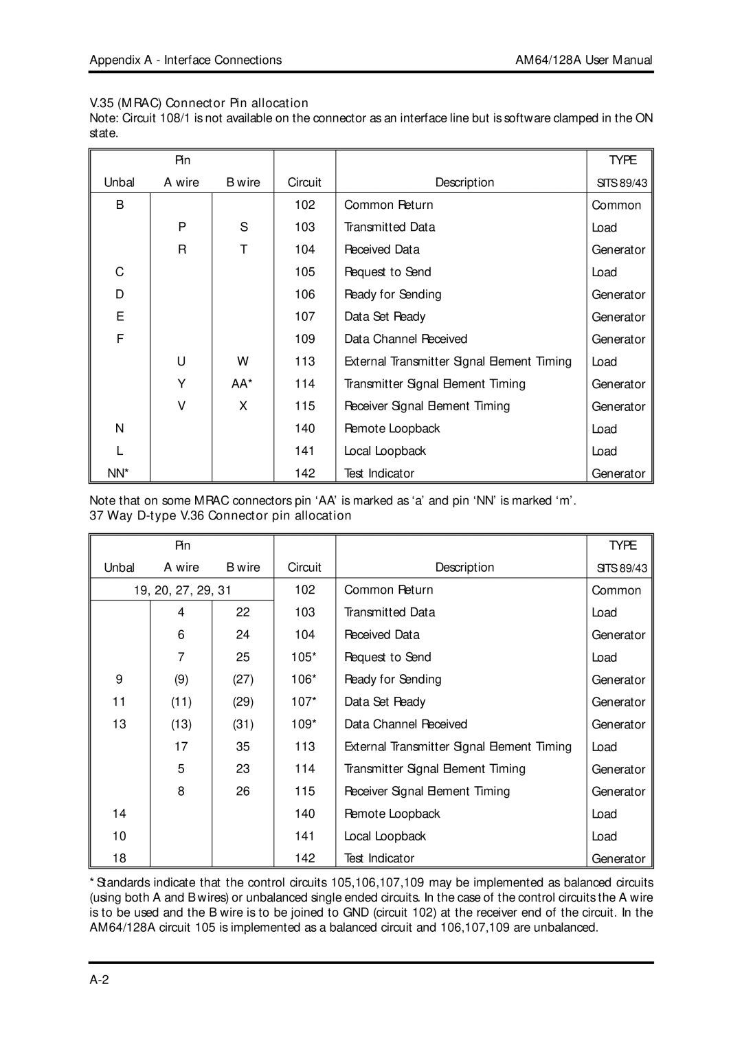
V.35 (MRAC) Connector Pin allocation
Note: Circuit 108/1 is not available on the connector as an interface line but is software clamped in the ON state.
| Pin |
|
|
| TYPE |
Unbal | A wire | B wire | Circuit | Description | SITS 89/43 |
|
|
|
|
|
|
B |
|
| 102 | Common Return | Common |
| P | S | 103 | Transmitted Data | Load |
| R | T | 104 | Received Data | Generator |
C |
|
| 105 | Request to Send | Load |
D |
|
| 106 | Ready for Sending | Generator |
E |
|
| 107 | Data Set Ready | Generator |
F |
|
| 109 | Data Channel Received | Generator |
| U | W | 113 | External Transmitter Signal Element Timing | Load |
| Y | AA* | 114 | Transmitter Signal Element Timing | Generator |
| V | X | 115 | Receiver Signal Element Timing | Generator |
N |
|
| 140 | Remote Loopback | Load |
L |
|
| 141 | Local Loopback | Load |
NN* |
|
| 142 | Test Indicator | Generator |
|
|
|
|
|
|
Note that on some MRAC connectors pin ‘AA’ is marked as ‘a’ and pin ‘NN’ is marked ‘m’.
37 Way D-type V.36 Connector pin allocation
| Pin |
|
|
| TYPE |
Unbal | A wire | B wire | Circuit | Description | SITS 89/43 |
|
|
|
|
|
|
19, 20, 27, 29, 31 | 102 | Common Return | Common | ||
|
|
| 103 |
|
|
| 4 | 22 | Transmitted Data | Load | |
| 6 | 24 | 104 | Received Data | Generator |
| 7 | 25 | 105* | Request to Send | Load |
9 | (9) | (27) | 106* | Ready for Sending | Generator |
11 | (11) | (29) | 107* | Data Set Ready | Generator |
13 | (13) | (31) | 109* | Data Channel Received | Generator |
| 17 | 35 | 113 | External Transmitter Signal Element Timing | Load |
| 5 | 23 | 114 | Transmitter Signal Element Timing | Generator |
| 8 | 26 | 115 | Receiver Signal Element Timing | Generator |
14 |
|
| 140 | Remote Loopback | Load |
10 |
|
| 141 | Local Loopback | Load |
18 |
|
| 142 | Test Indicator | Generator |
|
|
|
|
|
|
*Standards indicate that the control circuits 105,106,107,109 may be implemented as balanced circuits (using both A and B wires) or unbalanced single ended circuits. In the case of the control circuits the A wire is to be used and the B wire is to be joined to GND (circuit 102) at the receiver end of the circuit. In the AM64/128A circuit 105 is implemented as a balanced circuit and 106,107,109 are unbalanced.