Constructional Details | AM64/128A User Manual |
| |
2.CONSTRUCTIONAL DETAILS
2.1Baseband Modems
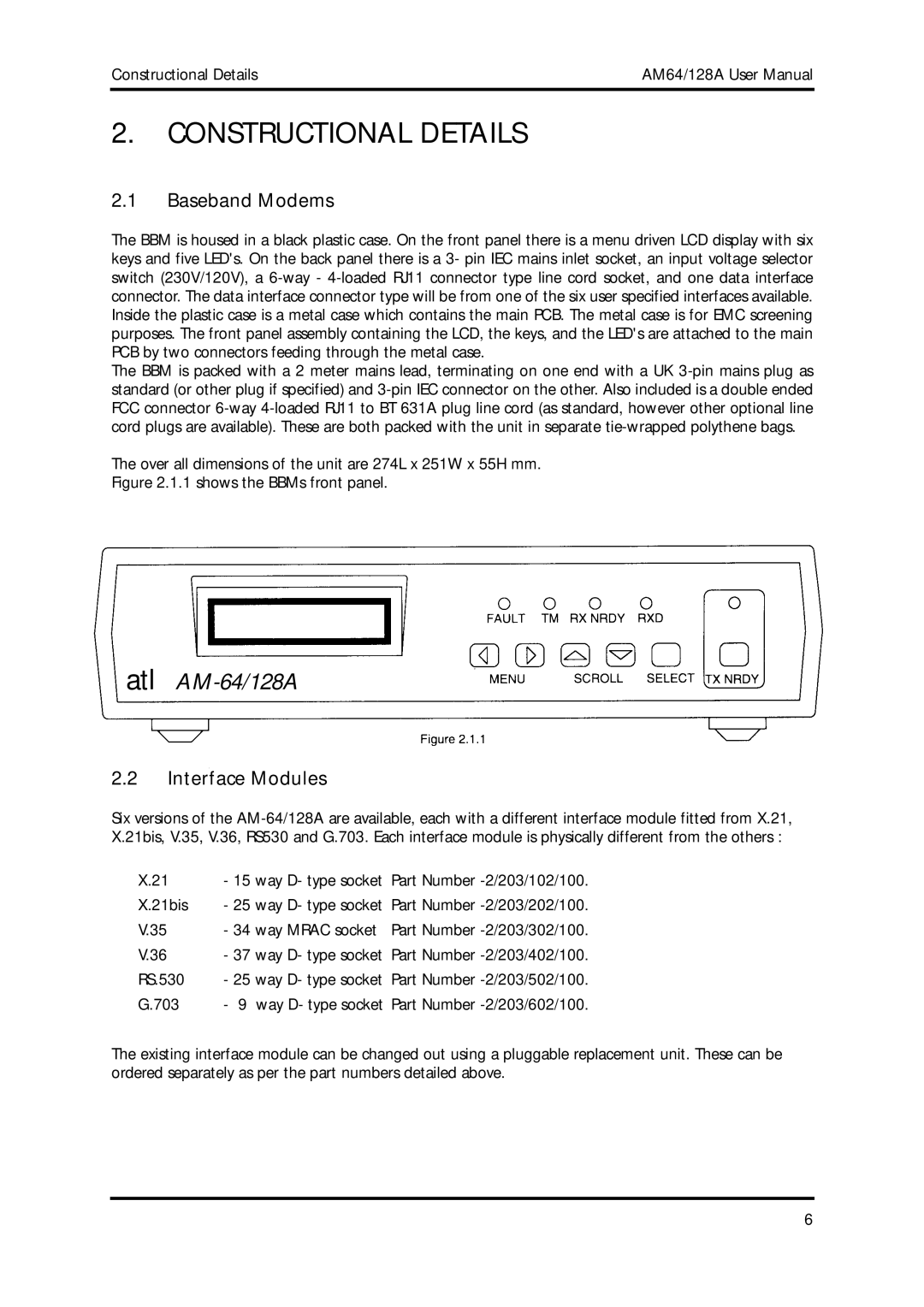
The BBM is housed in a black plastic case. On the front panel there is a menu driven LCD display with six keys and five LED's. On the back panel there is a 3- pin IEC mains inlet socket, an input voltage selector switch (230V/120V), a 6-way - 4-loaded RJ11 connector type line cord socket, and one data interface connector. The data interface connector type will be from one of the six user specified interfaces available. Inside the plastic case is a metal case which contains the main PCB. The metal case is for EMC screening purposes. The front panel assembly containing the LCD, the keys, and the LED's are attached to the main PCB by two connectors feeding through the metal case.
The BBM is packed with a 2 meter mains lead, terminating on one end with a UK 3-pin mains plug as standard (or other plug if specified) and 3-pin IEC connector on the other. Also included is a double ended FCC connector 6-way 4-loaded RJ11 to BT 631A plug line cord (as standard, however other optional line cord plugs are available). These are both packed with the unit in separate tie-wrapped polythene bags.
The over all dimensions of the unit are 274L x 251W x 55H mm.
Figure 2.1.1 shows the BBMs front panel.
atl AM-64/128A
2.2Interface Modules
Six versions of the AM-64/128A are available, each with a different interface module fitted from X.21, X.21bis, V.35, V.36, RS530 and G.703. Each interface module is physically different from the others :
X.21 | - 15 way D- type socket | Part Number -2/203/102/100. |
X.21bis | - 25 way D- type socket | Part Number -2/203/202/100. |
V.35 | - 34 way MRAC socket | Part Number -2/203/302/100. |
V.36 | - 37 way D- type socket | Part Number -2/203/402/100. |
RS.530 | - 25 way D- type socket | Part Number -2/203/502/100. |
G.703 | - 9 way D- type socket Part Number -2/203/602/100. |
The existing interface module can be changed out using a pluggable replacement unit. These can be ordered separately as per the part numbers detailed above.