AM64/128A User Manual | Appendix B – Internal Link Settings |
|
|
Interface Modules
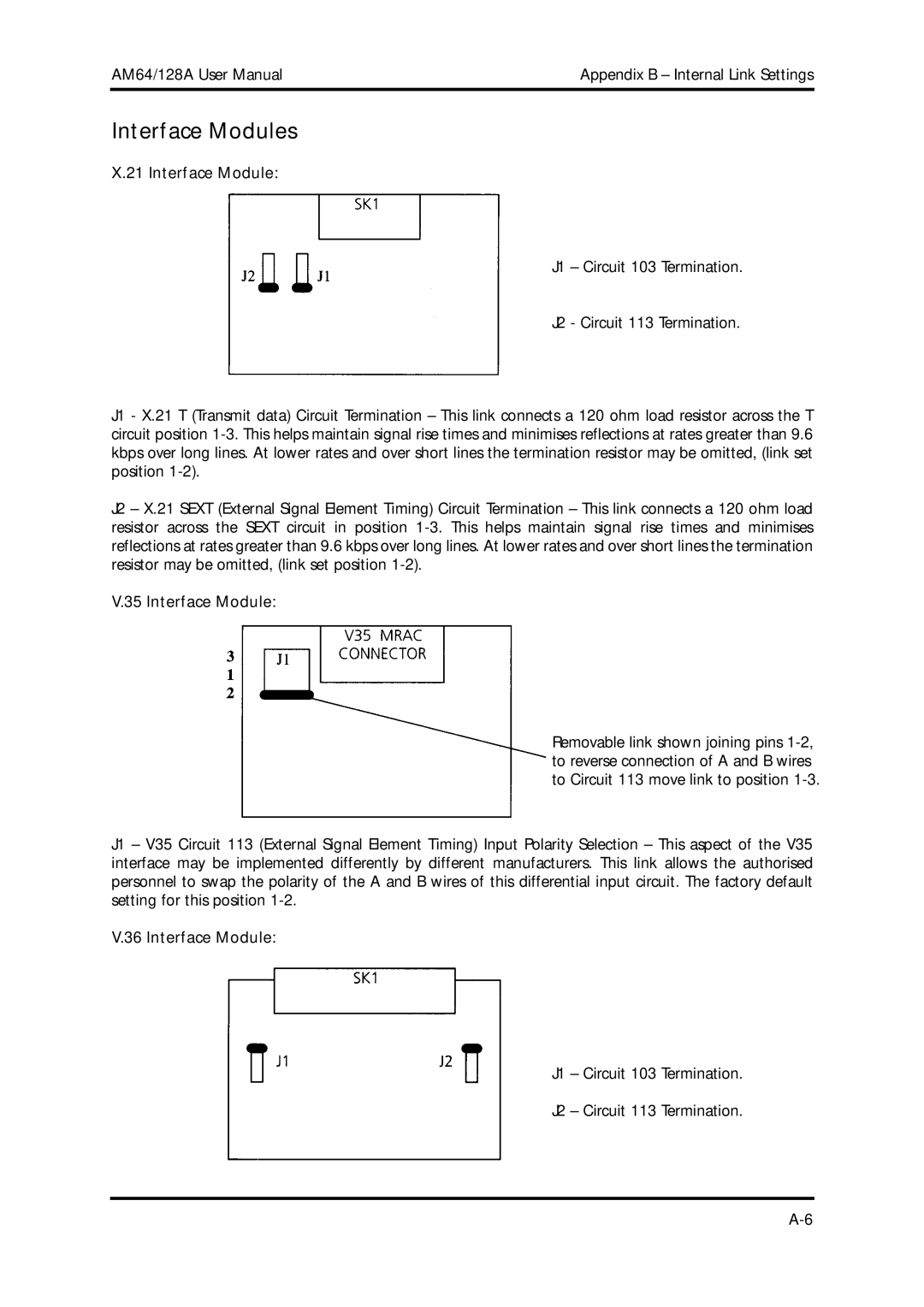
X.21 Interface Module:
J1 – Circuit 103 Termination.
J2 - Circuit 113 Termination.
J1 - X.21 T (Transmit data) Circuit Termination – This link connects a 120 ohm load resistor across the T circuit position
J2 – X.21 SEXT (External Signal Element Timing) Circuit Termination – This link connects a 120 ohm load resistor across the SEXT circuit in position
V.35 Interface Module:
Removable link shown joining pins
J1 – V35 Circuit 113 (External Signal Element Timing) Input Polarity Selection – This aspect of the V35 interface may be implemented differently by different manufacturers. This link allows the authorised personnel to swap the polarity of the A and B wires of this differential input circuit. The factory default setting for this position
V.36 Interface Module:
J1 – Circuit 103 Termination.
J2 – Circuit 113 Termination.