AM 64/128A User Manual | Appendix B – Internal Link Settings |
|
|
Interface Modules:
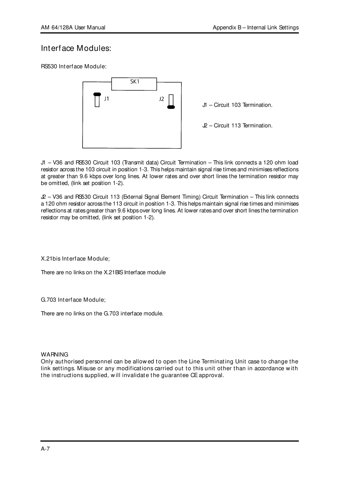
RS530 Interface Module:
J1 – Circuit 103 Termination.
J2 – Circuit 113 Termination.
J1 – V36 and RS530 Circuit 103 (Transmit data) Circuit Termination – This link connects a 120 ohm load resistor across the 103 circuit in position
J2 – V36 and RS530 Circuit 113 (External Signal Element Timing) Circuit Termination – This link connects a 120 ohm resistor across the 113 circuit in position
X.21bis Interface Module;
There are no links on the X.21BIS Interface module
G.703 Interface Module;
There are no links on the G.703 interface module.
WARNING
Only authorised personnel can be allowed to open the Line Terminating Unit case to change the link settings. Misuse or any modifications carried out to this unit other than in accordance with the instructions supplied, will invalidate the guarantee CE approval.