20 mA CURRENT LOOP SERIAL COMMUNICATIONS (Optional)
GENERAL DESCRIPTION
The serial communication option is a
Note: When operating the unit with a printer, the receive loop of the indicator must have current flowing into it before transmission can take place.
COMMUNICATION FORMAT
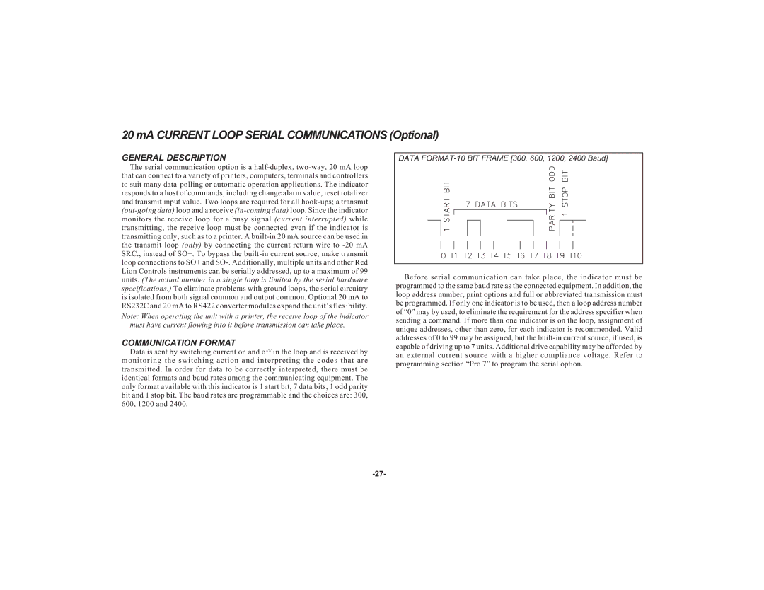
Data is sent by switching current on and off in the loop and is received by monitoring the switching action and interpreting the codes that are transmitted. In order for data to be correctly interpreted, there must be identical formats and baud rates among the communicating equipment. The only format available with this indicator is 1 start bit, 7 data bits, 1 odd parity bit and 1 stop bit. The baud rates are programmable and the choices are: 300, 600, 1200 and 2400.
DATA FORMAT-10 BIT FRAME [300, 600, 1200, 2400 Baud]
Before serial communication can take place, the indicator must be programmed to the same baud rate as the connected equipment. In addition, the loop address number, print options and full or abbreviated transmission must be programmed. If only one indicator is to be used, then a loop address number of “0” may by used, to eliminate the requirement for the address specifier when sending a command. If more than one indicator is on the loop, assignment of unique addresses, other than zero, for each indicator is recommended. Valid addresses of 0 to 99 may be assigned, but the