Apollo IMY instruction manual RE-TRANSMITTED Analog Output Optional

Models: IMY

1 48
Download 48 pages 5.11 Kb
Page 35
Image 35

RE-TRANSMITTED ANALOG OUTPUT (Optional)

The re-transmitted analog output option transmits a digitally programmable 4 to 20 mA or 0 to 10 VDC signal to drive chart recorders, remote indicators and controllers. The option is contained on the upper PCB and has two outputs, “ANALOG-” (TBB #10) and “ANALOG+” (TBB #11) and is self-powered (active) with a compliance of 10 VDC. The analog “-” output is isolated from the input common, eliminating problems from ground loops. Programming of the option is performed in “Pro 8” of the normal programming mode. Display values are simply keyed in to provide a 4 mA or

0VDC output, “AN-Lo”, and a 20 mA or 10 VDC output, “AN-HI”. The analog output then follows the assigned value and as such will update every measurement cycle. Nonstandard current or voltage ranges can be supported

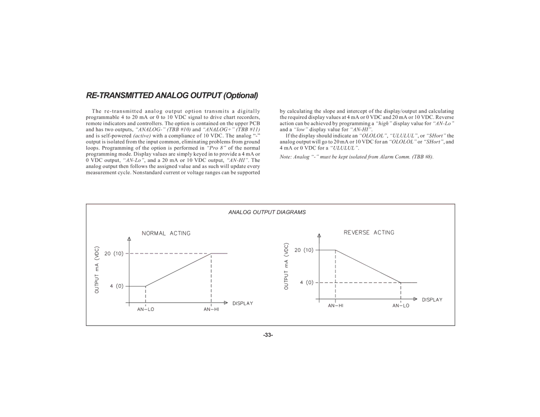
by calculating the slope and intercept of the display/output and calculating the required display values at 4 mA or 0 VDC and 20 mA or 10 VDC. Reverse action can be achieved by programming a “high” display value for “AN-Lo”and a “low” display value for “AN-HI”.

If the display should indicate an “OLOLOL”, “ULULUL”, or “SHort” the analog output will go to 20 mA or 10 VDC for an “OLOLOL” or “SHort”, and 4 mA or 0 VDC for a “ULULUL”.

Note: Analog “-” must be kept isolated from Alarm Comm. (TBB #8).

ANALOG OUTPUT DIAGRAMS

-33-

Page 35
Image 35
Apollo IMY instruction manual RE-TRANSMITTED Analog Output Optional