installation
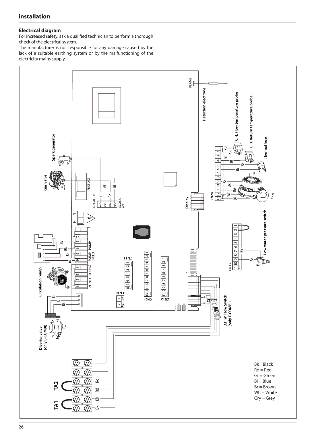
Electrical diagram
For increased safety, ask a qualified technician to perform a thorough check of the electrical system.
The manufacturer is not responsible for any damage caused by the lack of a suitable earthing system or by the malfunctioning of the electricity mains supply.
|
|
| Spark generator |
|
|
|
|
|
|
|
|
|
|
|
|
|
| |
| Gas valve |
|
|
|
|
|
|
|
|
|
|
|
|
| FUSE 2AT | |||
|
|
|
|
|
|
|
|
|
|
|
|
|
|
|
|
|
| ACCENDITORE |
|
|
|
|
|
|
|
|
|
|
|
|
|
| L |
| |||
|
|
|
|
|
|
|
|
|
|
|
|
|
|
|
|
|
|
|
|
|
|
|
|
|
|
|
|
|
|
|
|
| N |
| |||
|
|
|
|
|
|
|
|
|
|
|
|
|
| 1 |
| 1 | ||
|
|
|
|
|
|
|
|
|
|
|
|
|
|
|
| |||
|
|
|
|
|
|
|
|
|
|
|
|
|
| 2 |
|
| ||
|
|
|
|
|
|
|
|
| 3 4 |
|
| |||||||
|
|
|
|
|
| Bk |
|
| PUMP | |||||||||
| 4 |
|
|
|
|
|
|
|
| Bk |
|
| ||||||
1 | 312 |
|
|
|
|
|
|
|
|
|
|
| Bk | 56 |
| PUMP SPEED | ||
|
|
|
|
|
|
|
|
|
|
|
| |||||||
|
|
|
|
|
|
|
|
|
|
| Bk |
|
|
|
|
| ||
|
|
|
|
|
|
|
|
|
|
|
|
|
|
|
|
|
| 1 |
|
|
|
|
|
|
|
|
|
|
|
|
|
|
|
|
|
| |
|
|
|
|
|
|
|
|
|
|
|
|
|
|
|
|
|
| |
|
|
|
|
|
|
|
|
|
|
|
|
|
|
|
|
|
| |
pump |
|
|
|
|
|
|
|
|
|
|
|
|
| 1 2 |
| FILLING | ||
Circulation |
|
|
|
|
|
|
|
|
|
|
|
|
| 3 4 |
| ZONE1 | ||
|
|
|
|
|
|
|
|
|
|
|
|
|
| |||||
|
|
|
|
|
|
|
|
|
|
|
|
|
|
|
|
|
| |
|
| Br |
|
|
|
|
|
|
|
|
|
|
|
|
|
|
| |
|
|
|
|
|
|
|
|
|
|
|
|
|
|
|
|
| ||
|
|
|
|
| Bl |
|
|
|
|
|
|
|
|
|
|
|
| |
|
|
|
|
|
|
|
|
|
|
|
|
|
|
|
|
| ||
Diverter valve | (only | Bk |
|
|
|
|
| |||||||||||
|
|
|
|
|
|
|
|
|
|
| ||||||||
|
|
|
|
|
|
|
|
|
|
| ||||||||
|
|
|
|
|
|
|
|
|
|
|
|
|
| |||||
|
|
| Bl |
|
| Bl |
| |
|
|
|
|
|
|
|
| |
|
|
|
|
|
|
|
| |
| Br |
|
| Br |
|
| VALVOLA GAS | |
|
|
|
|
|
|
| ||
|
|
|
|
|
|
| ||
1 | 2 | 3 | 4 | |||||
| ||||||||
CN11 12 ![]() 34 56 78
34 56 78 ![]()
16CN 1 ![]() 2
2
FLAME |
|
electrode | |
| Detection |
Display | 1 |
5 |
7 6 5 4 3 2 1 | 5 4 3 2 1 | 1 |
|
1110 9 8 | 9 8 7 6 |
|
|
1312 | 1110 | 1 |
|
Bk | |||
24CN | 12CN |
|
|
|
| ||
| Bk | ||
|
|
| |
|
|
|
|
|
|
|
|
|
|
|
|
|
|
|
|
|
|
|
|
| C.H. Flow temperature probe |
|
|
|
|
| C.H. Return temperature probe | Thermal fuse | ||||||||||||
| 3 2 1 |
|
|
|
|
| Rd |
|
|
|
|
|
|
|
|
|
|
|
|
|
|
|
|
|
|
|
| |||||||||
|
|
|
|
|
|
|
| Rd |
|
|
|
|
|
|
|
|
|
|
|
|
|
|
|
|
|
|
|
| ||||||||
|
|
|
|
|
|
|
|
|
|
|
|
|
|
|
|
|
|
|
|
|
|
|
|
|
|
|
|
|
|
|
| |||||
|
|
|
|
|
| Bl |
|
|
|
|
|
|
|
|
|
|
|
|
|
|
|
|
|
|
|
|
|
|
| |||||||
|
|
|
|
|
|
|
|
|
|
|
|
|
|
|
|
|
|
|
|
|
|
|
|
|
|
|
|
|
|
|
| |||||
| 5 4 |
|
|
|
|
|
|
|
| Bl |
|
|
|
|
|
|
|
|
|
|
|
|
|
|
|
|
|
|
|
| ||||||
|
|
|
|
|
|
|
|
|
|
|
|
|
|
|
|
|
|
|
|
|
|
|
|
|
|
|
|
|
|
|
|
| ||||
|
|
|
|
|
|
|
|
|
|
|
|
|
|
|
|
|
|
|
|
|
|
| Br |
|
|
|
|
|
| |||||||
|
|
|
|
|
|
|
|
|
|
|
|
|
|
|
|
|
|
|
|
|
|
|
|
|
|
|
|
|
|
|
| |||||
| 6 |
|
|
|
|
|
|
|
|
|
|
|
|
|
|
|
|
|
|
| Br |
|
|
|
|
|
|
|
|
|
|
| ||||
|
|
|
|
|
|
|
|
|
|
|
|
|
|
|
|
|
|
|
|
|
|
|
|
|
|
|
|
|
|
| ||||||
|
|
|
|
|
|
|
|
|
|
|
|
|
|
|
|
|
|
|
|
|
|
|
|
|
|
|
|
|
|
| ||||||
| 9 8 7 |
|
|
|
|
|
|
|
|
|
|
|
|
|
|
|
|
|
|
|
|
|
|
|
|
|
|
|
|
| ||||||
|
|
|
|
|
|
|
|
|
|
|
|
|
|
|
|
|
|
|
|
|
|
|
|
|
|
|
|
|
|
|
|
| ||||
|
|
|
| Br |
|
|
|
|
|
|
|
|
|
|
|
|
|
|
|
|
|
|
|
|
|
|
|
|
|
|
|
| ||||
|
|
|
| Bk |
|
|
|
|
|
|
|
|
|
|
|
|
|
|
|
|
|
|
|
|
| |||||||||||
| 13121110 |
|
|
|
|
|
|
|
|
|
|
|
|
|
|
|
|
|
|
|
|
|
|
|
|
|
|
|
|
|
| |||||
|
|
|
|
|
|
|
|
|
|
|
|
|
|
|
|
|
|
|
|
|
|
|
|
|
|
|
|
|
|
| ||||||
|
|
|
|
|
|
|
|
|
|
|
|
|
|
| Rd |
|
|
|
|
|
|
|
|
|
|
|
|
|
|
| ||||||
|
|
|
|
|
|
|
|
|
|
|
|
|
|
|
|
|
|
|
|
|
|
|
|
|
|
|
|
|
| |||||||
|
|
|
|
|
|
|
|
|
|
|
|
|
|
|
|
|
|
|
|
|
|
|
| |||||||||||||
CN24 |
|
|
|
|
|
| Wh |
|
|
|
|
|
|
|
|
|
|
|
|
|
| Fan | ||||||||||||||
|
|
|
|
|
|
|
|
|
|
|
|
|
|
|
|
|
|
|
| |||||||||||||||||
|
|
|
|
|
|
|
| Bl |
|
|
|
|
|
|
|
|
|
|
|
|
|
| ||||||||||||||
|
|
|
|
|
|
|
|
|
|
|
|
|
|
|
|
|
|
|
|
|
|
|
|
|
|
|
| |||||||||
|
|
|
|
|
|
|
|
|
|
|
|
|
|
|
|
|
|
|
|
|
|
|
|
|
|
|
|
|
|
| pressure switch | |||||
|
|
|
|
|
|
|
|
|
|
|
|
|
|
|
| 3 2 1 |
|
|
|
|
|
|
|
|
|
|
|
|
|
| ||||||
|
|
|
|
|
|
|
|
|
|
|
|
|
|
|
| 8 7 6 5 4 |
|
|
|
|
| Low water | ||||||||||||||
|
|
|
|
|
|
|
|
|
|
|
|
|
|
|
|
|
|
|
| Bk |
| |||||||||||||||
|
|
|
|
|
|
|
|
|
|
|
|
|
|
|
|
|
|
|
|
|
|
|
|
|
|
|
|
|
| |||||||
|
|
|
|
|
|
|
|
|
|
|
|
|
|
|
|
|
|
|
|
|
|
|
|
|
| Br |
|
|
|
| ||||||
|
|
|
|
|
|
|
|
|
|
|
|
|
|
|
| 9 |
|
|
|
|
|
|
|
|
|
|
|
|
| |||||||
|
|
|
|
|
|
|
|
|
|
|
|
|
|
|
|
|
|
|
|
|
|
|
|
|
|
|
| |||||||||
|
|
|
|
|
|
|
|
|
|
|
| CN12 | 1110 |
|
|
|
|
|
|
|
|
|
|
|
|
|
|
| ||||||||
|
|
|
|
|
|
|
|
|
|
|
|
|
|
|
|
|
|
|
|
|
|
|
|
|
|
| ||||||||||
Flow Switch | |
D.H.W. | (only E |
TA1 TA2
Bk Bk Rd Rd
Bk= Black
Rd = Red
Gr = Green
Bl = Blue
Br = Brown
Wh = White
Gry = Grey
26