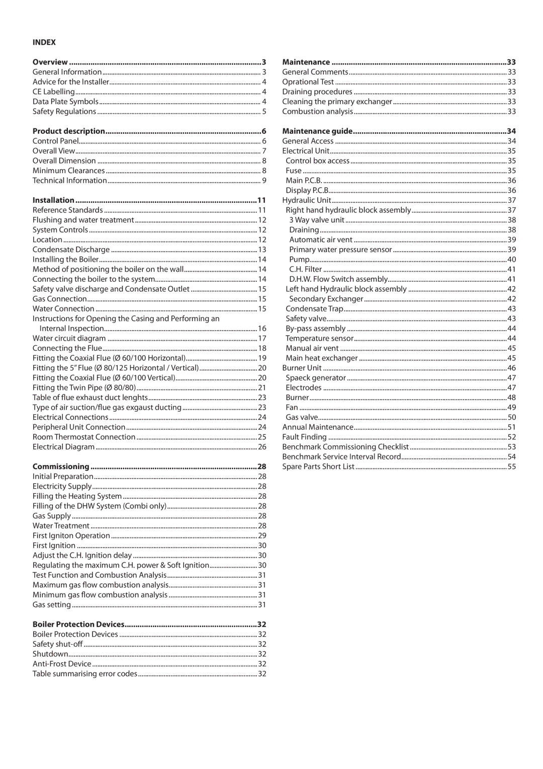
INDEX |
|
Overview | 3 |
General Information | 3 |
Advice for the Installer | 4 |
CE Labelling | 4 |
Data Plate Symbols | 4 |
Safety Regulations | 5 |
Product description | 6 |
Control Panel | 6 |
Overall View | 7 |
Overall Dimension | 8 |
Minimum Clearances | 8 |
Technical Information | 9 |
Installation | 11 |
Reference Standards | 11 |
Flushing and water treatment | 12 |
System Controls | 12 |
Location | 12 |
Condensate Discharge | 13 |
Installing the Boiler | 14 |
Method of positioning the boiler on the wall | 14 |
Connecting the boiler to the system | 14 |
Safety valve discharge and Condensate Outlet | 15 |
Gas Connection | 15 |
Water Connection | 15 |
Instructions for Opening the Casing and Performing an |
|
Internal Inspection | 16 |
Water circuit diagram | 17 |
Connecting the Flue | 18 |
Fitting the Coaxial Flue (Ø 60/100 Horizontal) | 19 |
Fitting the 5” Flue (Ø 80/125 Horizontal / Vertical) | 20 |
Fitting the Coaxial Flue (Ø 60/100 Vertical) | 20 |
Fitting the Twin Pipe (Ø 80/80) | 21 |
Table of flue exhaust duct lenghts | 23 |
Type of air suction/flue gas exgaust ducting | 23 |
Electrical Connections | 24 |
Peripheral Unit Connection | 24 |
Room Thermostat Connection | 25 |
Electrical Diagram | 26 |
Commissioning | 28 |
Initial Preparation | 28 |
Electricity Supply | 28 |
Filling the Heating System | 28 |
Filling of the DHW System (Combi only) | 28 |
Gas Supply | 28 |
Water Treatment | 28 |
First Igniton Operation | 29 |
First Ignition | 30 |
Adjust the C.H. Ignition delay | 30 |
Regulating the maximum C.H. power & Soft Ignition | 30 |
Test Function and Combustion Analysis | 31 |
Maximum gas flow combustion analysis | 31 |
Minimum gas flow combustion analysis | 31 |
Gas setting | 31 |
Boiler Protection Devices | 32 |
Boiler Protection Devices | 32 |
Safety | 32 |
Shutdown | 32 |
32 | |
Table summarising error codes | 32 |
Maintenance | 33 |
General Comments | 33 |
Oprational Test | 33 |
Draining procedures | 33 |
Cleaning the primary exchanger | 33 |
Combustion analysis | 33 |
Maintenance guide | 34 |
General Access | 34 |
Electrical Unit | 35 |
Control box access | 35 |
Fuse | 35 |
Main P.C.B | 36 |
Display P.C.B | 36 |
Hydraulic Unit | 37 |
Right hand hydraulic block assembly | 37 |
3 Way valve unit | 38 |
Draining | 38 |
Automatic air vent | 39 |
Primary water pressure sensor | 39 |
Pump | 40 |
C.H. Filter | 41 |
D.H.W. Flow Switch assembly | 41 |
Left hand Hydraulic block assembly | 42 |
Secondary Exchanger | 42 |
Condensate Trap | 43 |
Safety valve | 43 |
44 | |
Temperature sensor | 44 |
Manual air vent | 45 |
Main heat exchanger | 45 |
Burner Unit | 46 |
Spaeck generator | 47 |
Electrodes | 47 |
Burner | 48 |
Fan | 49 |
Gas valve | 50 |
Annual Maintenance | 51 |
Fault Finding | 52 |
Benchmark Commissioning Checklist | 53 |
Benchmark Service Interval Record | 54 |
Spare Parts Short List | 55 |
