installation
![]() WARNING
WARNING
Before performing any work on the boiler, first disconnect it from the electrical power supply using the external bipolar switch and remove the fuse.
Electrical connections
For increased safety, ask a qualified technician to perform a thorough check of the electrical system.
The manufacturer is not responsible for any damage caused by the lack of a suitable earthing system or by the malfunctioning of the electricity mains supply.
Make sure that the system is able to withstand the maximum power used by the boiler (this is indicated on the appliance data plate). Check that the section of the wires is suitable and is not less 0.75 mm2 The appliance must be connected to an efficient earthing system if it is to operate correctly.
The power supply cable must be connected to a
Important!
In the event that the power supply cable has to be changed, replace it with one with the same specification.
Power supply cable
120
H05V2V2-F
140
Important!
The appliance is supplied with a
by means of a 3A fused three pin plug and unswitched shuttered socket outlet both complying with BS1363.
The use of multiplugs, extension leads or adaptors is strictly prohibited. It is strictly forbidden to use the piping from the hydraulic, heating and gas systems for the appliance earthing connection.
The boiler is not protected against the effects caused by lightning. If the boiler fuses need to be replaced, use 2A rapid fuses.
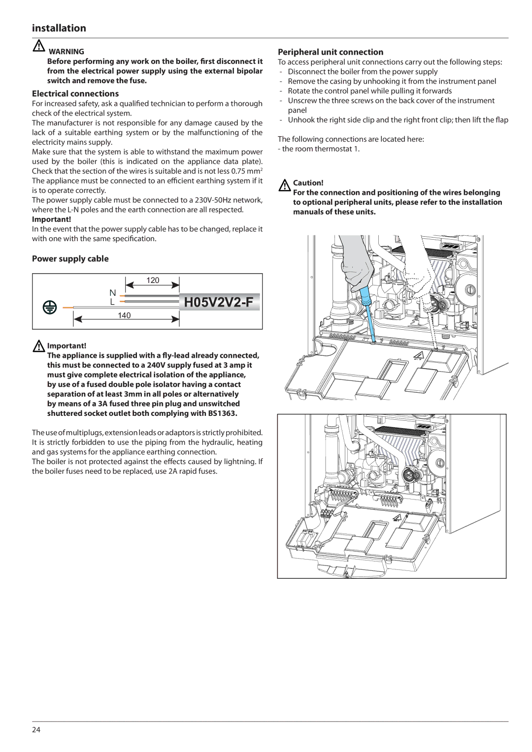
Peripheral unit connection
To access peripheral unit connections carry out the following steps:
-Disconnect the boiler from the power supply
-Remove the casing by unhooking it from the instrument panel
-Rotate the control panel while pulling it forwards
-Unscrew the three screws on the back cover of the instrument panel
-Unhook the right side clip and the right front clip; then lift the flap
The following connections are located here: - the room thermostat 1.
Caution!
For the connection and positioning of the wires belonging to optional peripheral units, please refer to the installation manuals of these units.
24