VSI-PRO
June
VSI-Pro
Contents
Contents
Gasboy Sub-Menu
Download/Upload Sub-Menu
Introduction
VSI / VSI+ / VSI-Pro Backward Compatibility
Features & Specifications
Features
Features & Specifications
Specifications
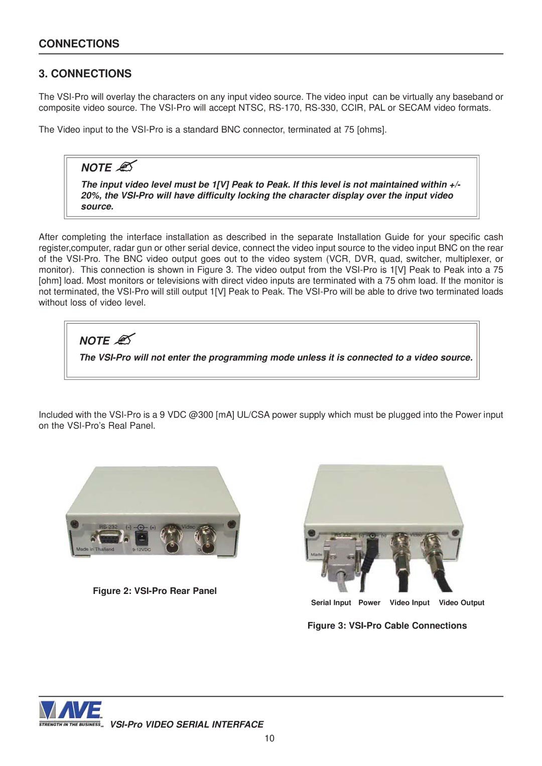
Connections
VSI-Pro Rear Panel
DTR
PIN # Signal Name RS232
PIN # Function Direction
DSR
VSI-PRO
VSI-Pro Connections
User Front Panel Controls
Front Panel Controls
Changing the Horizontal Position
Main Programming Menu
Programming
Getting Started
Register Select
Next page Exit
TCP/IP Limitations
Display Receipt Exit
SET Address ANY Exit
SET Address
Display
Device CON Sole Device Address Exit
Model
Display Journal Exit
Device
Local VSS Micros IDN Network Micros ISN Network Exit
Operator Customer Combined Exit
Journal Receipt Check Credit Exit
Device Printer Device Address ANY Modetap Exit
Woking Mode
Title Display on Console ID ANY Working Mode Exit
Model Working Mode Exit
NCR Jrnl Printer NCR Rcpt Printer NCR Slip Printer
Device Address ANY Address Exit
Model TK-T500 Mode Emulating Exit
Device Address Exit
Next page Exit
Journal Printer Receipt Printer
SET Term no
Choices ALL, 1, 2, 3,..., 253, 254
Choices RECEIPT, CDU 2L , C.D.U
Text Grayscale
Screen Setup
Background Grayscale
Clock Sub-Menu
Title
Text Display
Titler OFF Exit
Screen Blank Display Lines Display Format
Screen Blank
Choices NONE, 6, 12, 20, 30, 60, 120, 180
Line Compress
Left Justification
RS-232
Communication
Interface Type
Choices RS-232, Passive TAP, RS-485
Choices 7 or
Exception Reports
Choices NONE, ODD, Even
Exception Report Overview
ON-SCREEN Flags
Hard Alarm Output
Printer or DVR Output
Total Exception
Exception History SET Exception Output Time Stamp Exit
Exception History
Total Exceptions
Dest ID SCR ID Exit
Time Search Time Search Setting
DMS-3001 DVR-3011.3021
Choices 1 through
Example
Operator None Exit
0000.00
Exception no
History Buffer ON/OFF
Scroll Matching Exception Strings ON/OFF
Programming Note
Negative Exception
Page
Greater than
OUT Range
Less than
Exception Report Menu Output
Alarm Outputs
Alarm no
Triggered Text Exit
Normal State
RTS
Choices no Normally open, NC Normal closed
Display Text OFF Output Text SET Triggered Exit
Choices 6, 12, 30, 60, 120, 180
Triggered Text
Display Text
Display Text OFF Output Text SET Triggered Text Exit
TEST/DEMO Mode
SET Triggered Text
Port 1 Test Data Capture Register Demo Version ID Exit
Port 1 Test
Receive RX Test
RX / TX Test
RX /TX Test Display
RX Baudrate Auto TX Baudrate
Capture to Port Capture to Memory Dump Memory Exit
Capture to Port
2400
VSI-PRO Version 13.00R19 03/25/2008
DOWNLOAD/UPLOAD Setup
Demo Demo on Power UP OFF Exit
DOWNLOAD/UPLOAD Data Cable
DOWNLOAD/UPLOAD Setup Using VSI-PRO to VSI-PRO
DOWNLOAD/UPLOAD Setup Using VSI-Pro to VSI-Pro
Download Setup Upload Setup Update Firmware Exit
Download Setup Upload Setup Exit
Software Installation
DOWNLOAD/UPLOAD Setup Using a PC
VSI-Pro Remote Program Downloading Ver
Click the Tab Remote and you will see the following Menu
Figure P2 Remote Menu
Communication Cable Pin Out
File Menu
About Menu
PC / Laptop VSI-Pro
VSI-Pro Firmware Download Menu
VSI-Pro Firmware Download Utility
Figure P6 Connect To Menu
Figure P8 In-System Programming Display
Problem Solving Guide
Appendix a
Appendix a
Problem Solving Guide
HOW to do a Master Reset on VSI-PRO
Characters JITTER, JUMP, or Skew
Front Panel
PC-BASED Cash Register
Appendix B
TXD RXD GND
DVR
Appendix C
Other
RS-485 Network
Appendix C
DB-9 Pin-Out RJ-45 Pin-Out
Physical Characteristics
RS-485 Network Data Cable Wiring
Electrical Characteristics
RS-232 Parameters
Hydra / Regcom Front Panel
Hydra / Regcom Rear Panel
Appendix D
RS-485 Networker
Appendix E
Appendix F
RS-485 Vnetworker
RS-485 Vnetworker
Figure Vnetworker Connection Diagram Vnetworker Software
Figure Time / Date Set up Menu Remote Keyboard
Vsib DB-9M VSI-Pro DB-9M
Vsib Installation
Appendix G
TXD RXD RTS CTS GND
ECR Interface Cards
Appendix H
Tcpip 232 Adapter
Appendix
Tcpip 232 Adapter
Tcpip DB-9M
Hard Alarm Output
Appendix J
Appendix K
VSI-Pro Version 13.00 Register Select Menu
Register Select
Appendix K
VSI-Pro Version 13.24 Register Select Menu
Master Reset
Appendix L
Limited Warranty
Appendix M
Limited Warranty
Appendix N
North America