AXIS P3367–VE Fixed Dome Network Camera
Hardware overview
Connectors
Network connector -
Audio in (pink) - 3.5 mm input for a mono microphone, or a
Audio out (green) - 3.5 mm output for audio (line level) that can be connected to a public address (PA) system or an active speaker with a
SD card slot - A standard or
Note
Before removal, the SD card should be unmounted to prevent corruption of recordings. To unmount the SD card, go to Setup > System Options > Storage > SD Card and click Unmount.
Control button - The control button is used for:
•Connecting to an AXIS Video Hosting System service. See page 37. To connect, press and hold the button for about 1 second until the Status LED flashes green.
•Connecting to AXIS Internet Dynamic DNS Service. See page 37. To connect, press and hold the button for about 3 seconds.
•Resetting the product to factory default settings. See page 43.
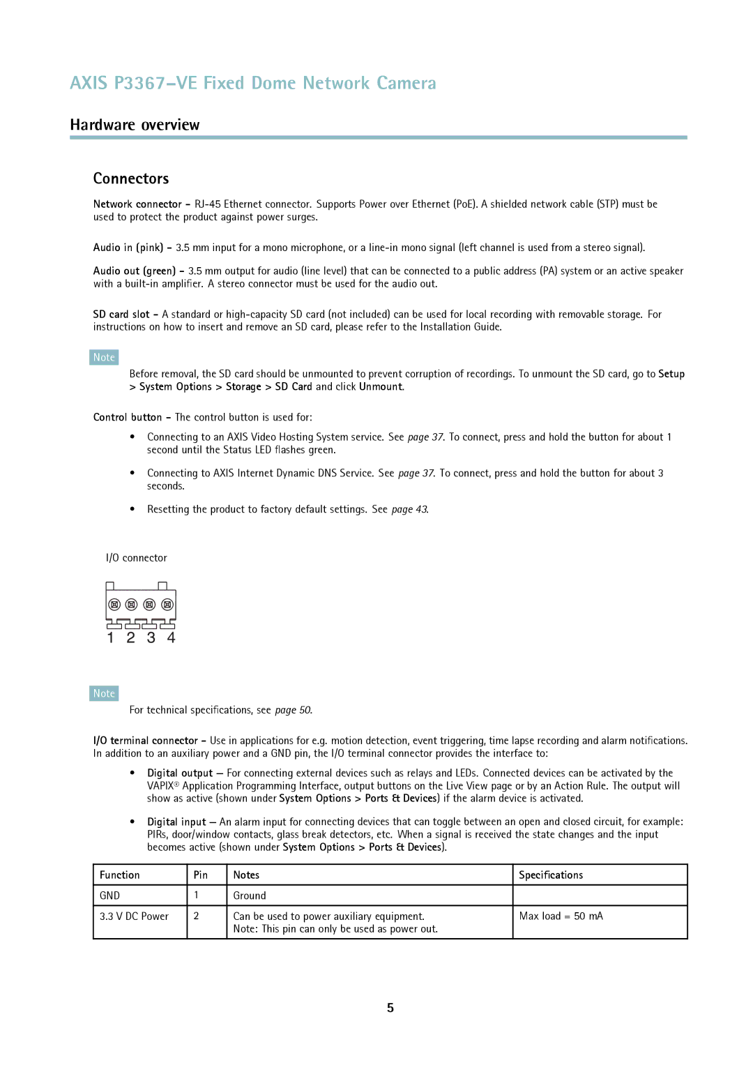
I/O connector
Note
For technical specifications, see page 50.
I/O terminal connector - Use in applications for e.g. motion detection, event triggering, time lapse recording and alarm notifications. In addition to an auxiliary power and a GND pin, the I/O terminal connector provides the interface to:
•Digital output — For connecting external devices such as relays and LEDs. Connected devices can be activated by the VAPIX® Application Programming Interface, output buttons on the Live View page or by an Action Rule. The output will show as active (shown under System Options > Ports & Devices) if the alarm device is activated.
•Digital input — An alarm input for connecting devices that can toggle between an open and closed circuit, for example: PIRs, door/window contacts, glass break detectors, etc. When a signal is received the state changes and the input becomes active (shown under System Options > Ports & Devices).
Function | Pin | Notes | Specifications |
|
|
|
|
GND | 1 | Ground |
|
|
|
|
|
3.3 V DC Power | 2 | Can be used to power auxiliary equipment. | Max load = 50 mA |
|
| Note: This pin can only be used as power out. |
|
|
|
|
|
5