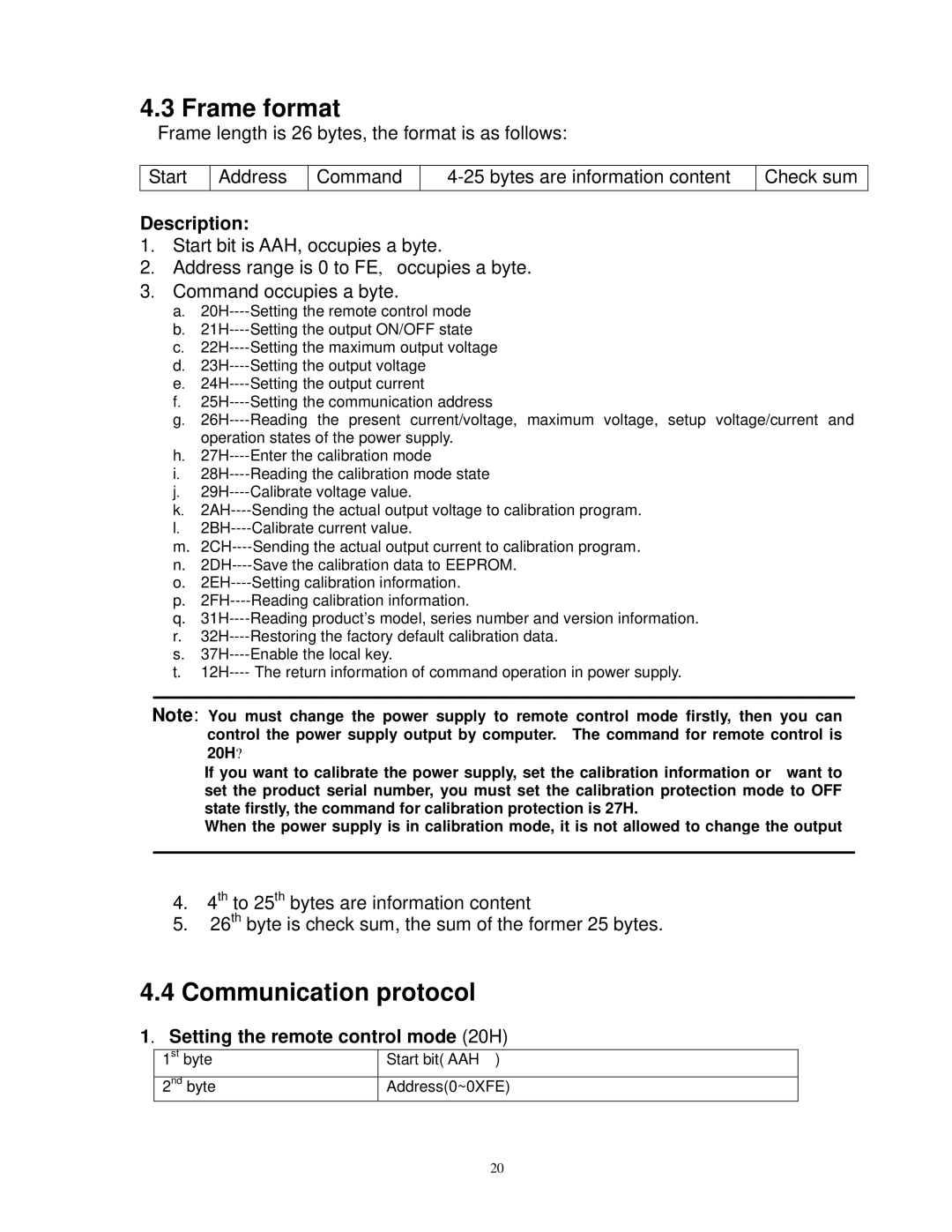
4.3 Frame format
Frame length is 26 bytes, the format is as follows:
Start
Address
Command
Check sum
Description:
1. Start bit is AAH, occupies a byte.
2. Address range is 0 to FE, occupies a byte.
3. Command occupies a byte.
a.
b.
c.
d.
e.
f.
g.
operation states of the power supply. h.
i.
j.
k.
l.
m.
n.
o.
p.
q.
r.
s.
t.
Note: You must change the power supply to remote control mode firstly, then you can control the power supply output by computer. The command for remote control is 20H?
If you want to calibrate the power supply, set the calibration information or want to set the product serial number, you must set the calibration protection mode to OFF state firstly, the command for calibration protection is 27H.
When the power supply is in calibration mode, it is not allowed to change the output
4.4th to 25th bytes are information content
5.26th byte is check sum, the sum of the former 25 bytes.
4.4Communication protocol
1. Setting the remote control mode (20H)
1st byte
2nd byte
Start bit( AAH )
Address(0~0XFE)
20
