5.1 Configuration
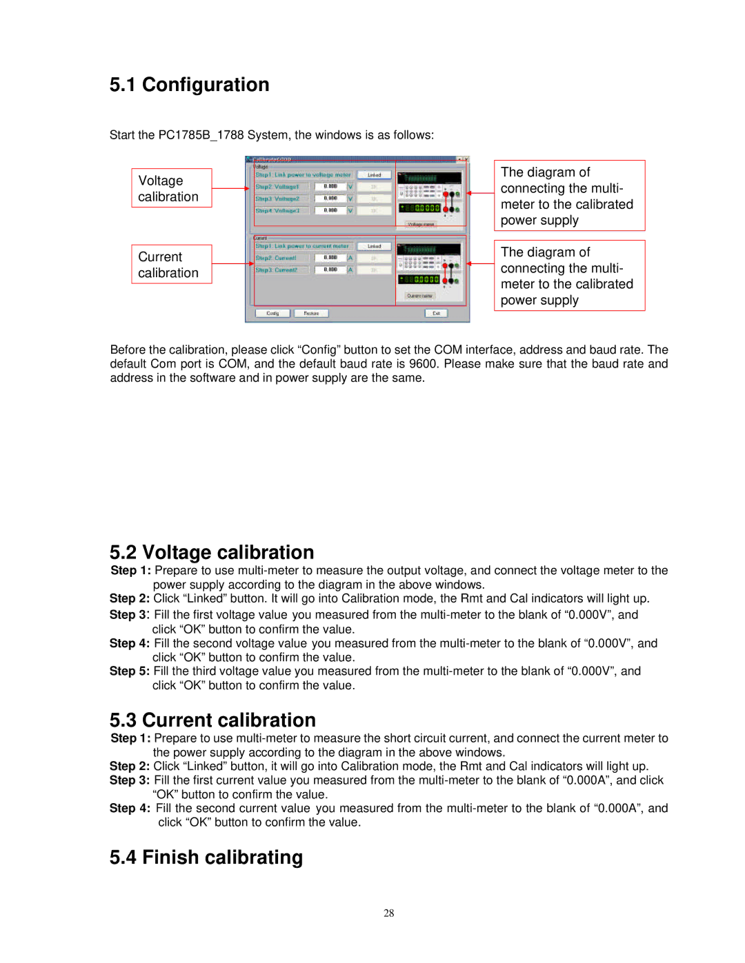
Start the PC1785B_1788 System, the windows is as follows:
Voltage calibration
Current calibration
The diagram of connecting the multi- meter to the calibrated power supply
The diagram of ![]() connecting the multi-
connecting the multi-
meter to the calibrated power supply
Before the calibration, please click “Config” button to set the COM interface, address and baud rate. The default Com port is COM, and the default baud rate is 9600. Please make sure that the baud rate and address in the software and in power supply are the same.
5.2 Voltage calibration
Step 1: Prepare to use
Step 2: Click “Linked” button. It will go into Calibration mode, the Rmt and Cal indicators will light up.
Step 3: Fill the first voltage value you measured from the
Step 4: Fill the second voltage value you measured from the
Step 5: Fill the third voltage value you measured from the
5.3 Current calibration
Step 1: Prepare to use
Step 2: Click “Linked” button, it will go into Calibration mode, the Rmt and Cal indicators will light up.
Step 3: Fill the first current value you measured from the
Step 4: Fill the second current value you measured from the
5.4 Finish calibrating
28