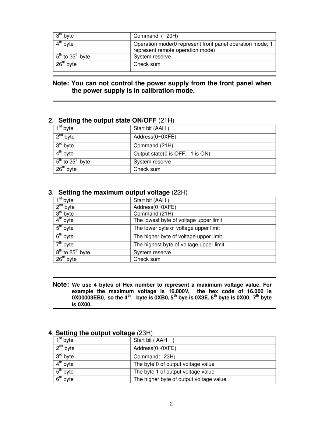
3rd byte | Command ( 20H) |
4th byte | Operation mode(0 represent front panel operation mode, 1 |
| represent remote operation mode) |
5th to 25th byte | System reserve |
26th byte | Check sum |
|
|
|
|
Note: You can not control the power supply from the front panel when the power supply is in calibration mode.
2. Setting the output state ON/OFF (21H)
1st byte | Start bit (AAH ) |
2nd byte | Address(0~0XFE) |
3rd byte | Command (21H) |
4th byte | Output state(0 is OFF, 1 is ON) |
5th to 25th byte | System reserve |
26th byte | Check sum |
3. Setting the maximum output voltage (22H)
1st byte | Start bit (AAH ) |
2nd byte | Address(0~0XFE) |
3rd byte | Command (21H) |
4th byte | The lowest byte of voltage upper limit |
5th byte | The lower byte of voltage upper limit |
6th byte | The higher byte of voltage upper limit |
7th byte | The highest byte of voltage upper limit |
8th to 25th byte | System reserve |
26th byte | Check sum |
Note: We use 4 bytes of Hex number to represent a maximum voltage value. For example the maximum voltage is 16.000V, the hex code of 16.000 is 0X00003EB0, so the 4th byte is 0XB0, 5th bye is 0X3E, 6th byte is 0X00, 7th byte is 0X00.
4. Setting the output voltage (23H)
1st byte | Start bit ( AAH ) |
2nd byte | Address(0~0XFE) |
3rd byte | Command( 23H) |
4th byte | The byte 0 of output voltage value |
5th byte | The byte 1 of output voltage value |
6th byte | The higher byte of output voltage value |
21