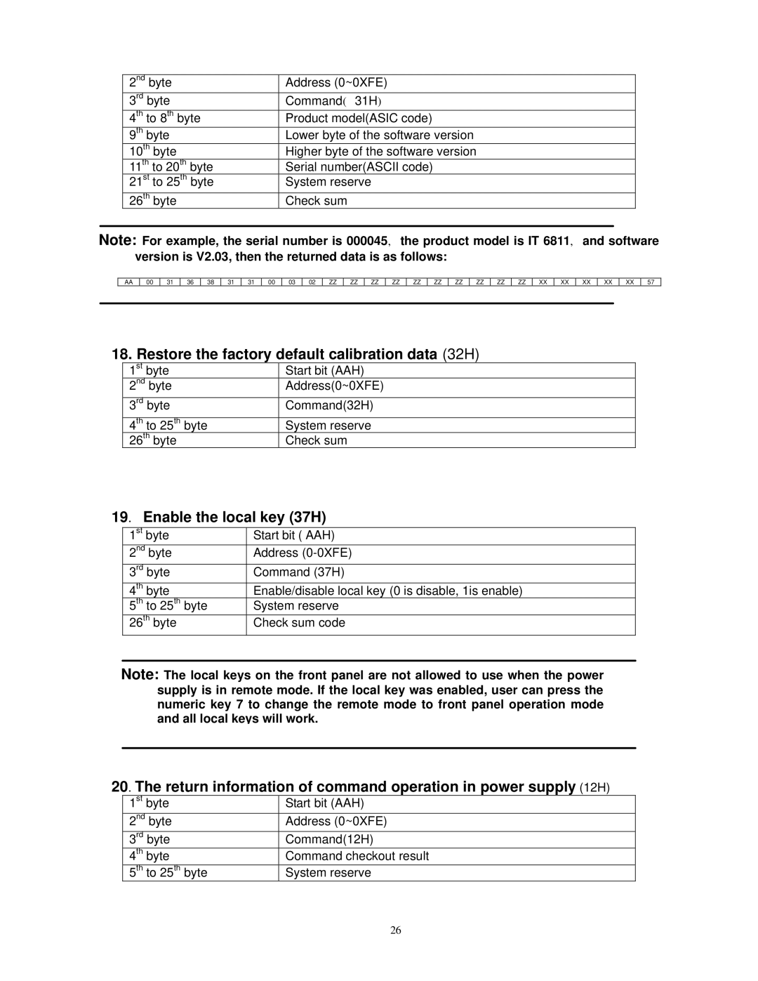
2nd byte | Address (0~0XFE) |
3rd byte | Command( 31H) |
4th to 8th byte | Product model(ASIC code) |
9th byte | Lower byte of the software version |
10th byte | Higher byte of the software version |
11th to 20th byte | Serial number(ASCII code) |
21st to 25th byte | System reserve |
26th byte | Check sum |
Note: For example, the serial number is 000045, the product model is IT 6811, and software version is V2.03, then the returned data is as follows:
AA | 00 | 31 | 36 | 38 | 31 | 31 | 00 | 03 | 02 | ZZ | ZZ | ZZ | ZZ | ZZ | ZZ |
ZZ ZZ ZZ ZZ XX XX
XX XX XX 57
18. Restore the factory default calibration data (32H)
1st byte | Start bit (AAH) |
2nd byte | Address(0~0XFE) |
3rd byte | Command(32H) |
4th to 25th byte | System reserve |
26th byte | Check sum |
19. Enable the local key (37H)
1st byte | Start bit ( AAH) |
2nd byte | Address |
3rd byte | Command (37H) |
4th byte | Enable/disable local key (0 is disable, 1is enable) |
5th to 25th byte | System reserve |
26th byte | Check sum code |
Note: The local keys on the front panel are not allowed to use when the power supply is in remote mode. If the local key was enabled, user can press the numeric key 7 to change the remote mode to front panel operation mode and all local keys will work.
20. The return information of command operation in power supply (12H)
1st byte | Start bit (AAH) |
2nd byte | Address (0~0XFE) |
3rd byte | Command(12H) |
4th byte | Command checkout result |
5th to 25th byte | System reserve |
26
