Connections
Fixed Slot (slot 1 & 2)
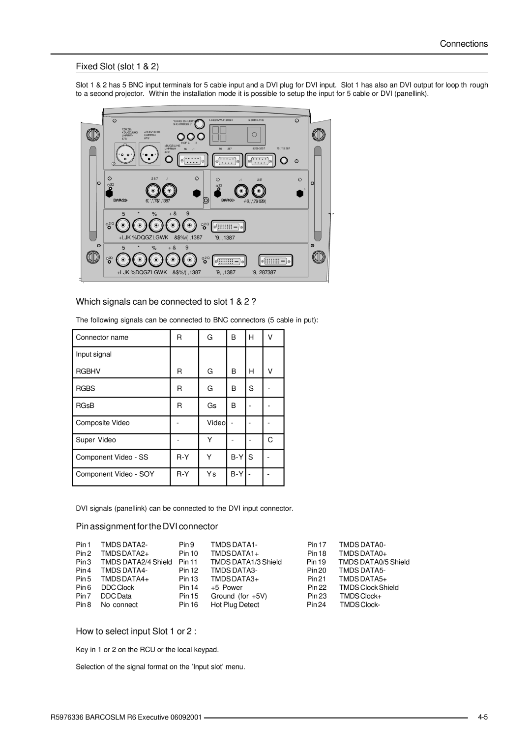
Slot 1 & 2 has BNC input terminals for 5 cable input and a DVI plug for DVI input. Slot 1 has also an DVI output for loop through to a second projector. Within the installation mode it is possible to setup the input for 5 cable or DVI (panellink).
Which signals can be connected to slot 1 & 2 ?
The following signals can be connected to BNC connectors (5 cable in put):
Connector name | R | G | B | H | V |
|
|
|
|
|
|
Input signal |
|
|
|
|
|
RGBHV | R | G | B | H | V |
|
|
|
|
|
|
RGBS | R | G | B | S | - |
|
|
|
|
|
|
RGsB | R | Gs | B | - | - |
|
|
|
|
|
|
Composite Video | - | Video | - | - | - |
|
|
|
|
|
|
Super Video | - | Y | - | - | C |
|
|
|
|
|
|
Component Video - SS | Y | S | - | ||
|
|
|
|
|
|
Component Video - SOY | Ys | - | - | ||
|
|
|
|
|
|
DVI signals (panellink) can be connected to the DVI input connector.
Pin assignment for the DVI connector
Pin 1 TMDS DATA2- | Pin 9 | TMDS DATA1- | Pin 17 TMDS DATA0- | ||
Pin 2 | TMDS DATA2+ | Pin 10 | TMDS DATA1+ | Pin 18 | TMDS DATA0+ |
Pin 3 TMDS DATA2/4 Shield | Pin 11 TMDS DATA1/3 Shield | Pin 19 | TMDS DATA0/5 Shield | ||
Pin 4 TMDS DATA4- | Pin 12 TMDS DATA3- | Pin 20 | TMDS DATA5- | ||
Pin 5 | TMDS DATA4+ | Pin 13 | TMDS DATA3+ | Pin 21 | TMDS DATA5+ |
Pin 6 | DDC Clock | Pin 14 | +5 Power | Pin 22 | TMDS Clock Shield |
Pin 7 | DDC Data | Pin 15 | Ground (for +5V) | Pin 23 | TMDSClock+ |
Pin 8 | No connect | Pin 16 Hot Plug Detect | Pin 24 | TMDS Clock- | |
How to select input Slot 1 or 2 :
Key in 1 or 2 on the RCU or the local keypad.
Selection of the signal format on the 'Input slot' menu.
R5976336 BARCOSLM R6 Executive 06092001 |
| |
|