In some cases, the supplied 6ft harness may not be sufficient for your installation. If this is the case, there is an optional 15 ft SmarTire Trailer-LinkTPMS Harness Part No: K075869 available. Please contact your distributor to order this part.

Step 7. Route the 4-pin diagnostic LED line to the side of the trailer or slider and secure the line every foot with zip ties. Ensure the Bendix diagnostics LED Cap part number K075866 is placed over the end of the diagnostic connector, P4 in Figure 17 when not used with the Maintenance Hand tool. Connect the trailer to power and watch for the LED to light up briefly to confirm the SmarTire Trailer-Link ECU is functional. Refer to the blink code table in Section C for more information.

Step 8. If needed, adjust the Cold Inflation Pressure (CIP) of each axle using the SmarTire® Maintenance Hand tool (090.0011) and diagnostics harness part number K092501 as described in Section 3.1 to complete the installation.

If the optional trailer warning lamp is not installed, please use the supplied dielectric grease and fill the trailer lamp output connector (P5 in Figure 17) with grease to protect it from corrosion. For instructions on how to install the optional trailer warning lamp, continue to step 9.

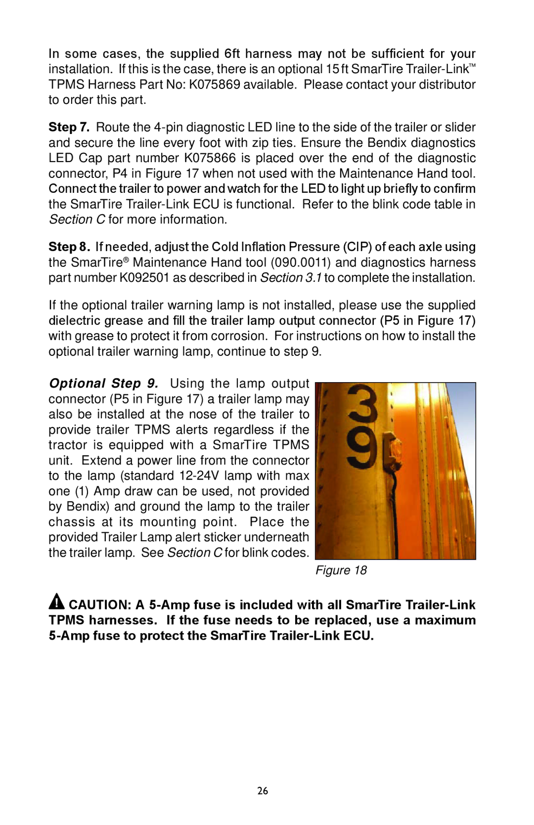
Optional Step 9. Using the lamp output connector (P5 in Figure 17) a trailer lamp may also be installed at the nose of the trailer to provide trailer TPMS alerts regardless if the tractor is equipped with a SmarTire TPMS unit. Extend a power line from the connector to the lamp (standard 12-24V lamp with max one (1) Amp draw can be used, not provided by Bendix) and ground the lamp to the trailer chassis at its mounting point. Place the provided Trailer Lamp alert sticker underneath the trailer lamp. See Section C for blink codes.

Figure 18

CAUTION: A 5-Amp fuse is included with all SmarTire Trailer-Link TPMS harnesses. If the fuse needs to be replaced, use a maximum 5-Amp fuse to protect the SmarTire Trailer-Link ECU.

26

Page 26
Image 26
BENDIX BW2920 manual