DESICCANT |
|
|
|
|
BED |
|
|
|
|
OIL |
|
|
| SPRING |
|
|
|
| |
SEPARATOR |
|
|
|
|
|
| DESICCANT |
| |
|
| CARTRIDGE |
| |
PURGE |
|
|
|
|
ORIFICE |
|
|
|
|
|
| PURGE |
| PIPE PLUG |
|
|
|
| |
CONTROL |
| VOLUME |
|
|
PORT |
|
|
|
|
SUPPLY |
| CHECK |
|
|
| VALVE |
|
| |
PORT |
|
|
| |
| (BLACK) |
|
| |
|
|
|
| |
TURBO |
|
|
| DELIVERY |
|
|
| PORT | |
VALVE |
|
| CARTRIDGE | |
PURGE |
|
|
| |
|
| BOLT | CHECK VALVE | |
VALVE |
| DELIVERY | ||
| CARTRIDGE |
| (WHITE) | |
| PORT |
| ||
| BOLT |
|
| |
|
|
|
| |
Old Style End Cover | New Style End Cover - Horizontal Delivery Check Valve | |||
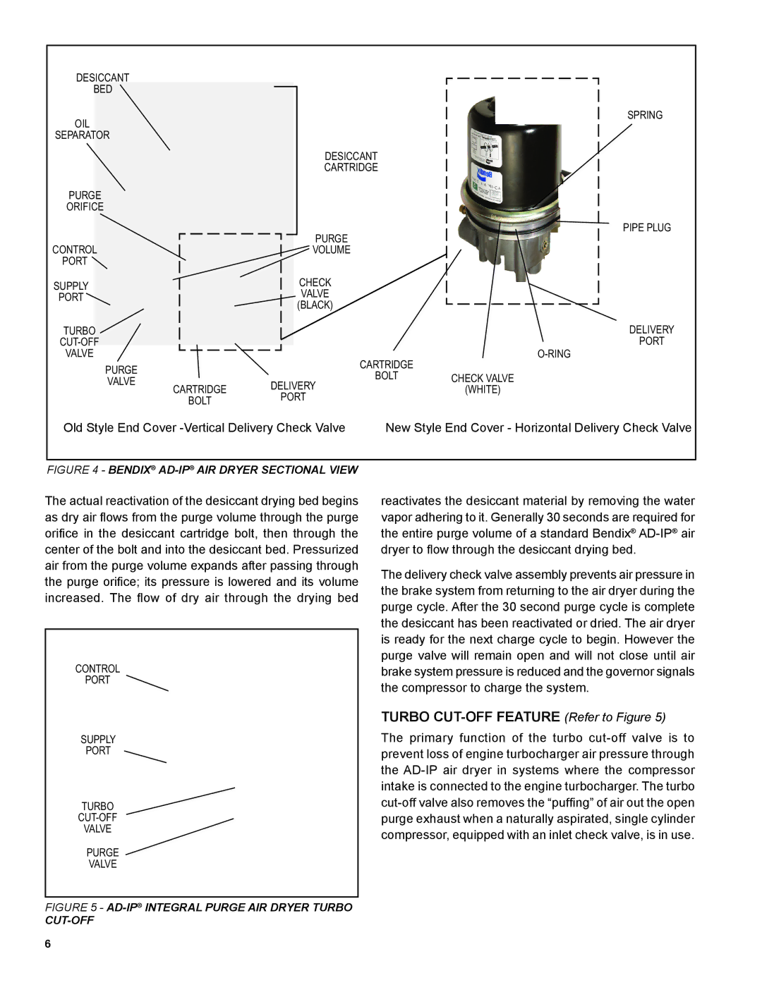
FIGURE 4 - BENDIX® AD-IP® AIR DRYER SECTIONAL VIEW
The actual reactivation of the desiccant drying bed begins as dry air flows from the purge volume through the purge orifice in the desiccant cartridge bolt, then through the center of the bolt and into the desiccant bed. Pressurized air from the purge volume expands after passing through the purge orifice; its pressure is lowered and its volume increased. The flow of dry air through the drying bed
CONTROL
PORT
SUPPLY
PORT
TURBO
VALVE
PURGE
VALVE
FIGURE 5 - AD-IP® INTEGRAL PURGE AIR DRYER TURBO
CUT-OFF
6
reactivates the desiccant material by removing the water vapor adhering to it. Generally 30 seconds are required for the entire purge volume of a standard Bendix®
The delivery check valve assembly prevents air pressure in the brake system from returning to the air dryer during the purge cycle. After the 30 second purge cycle is complete the desiccant has been reactivated or dried. The air dryer is ready for the next charge cycle to begin. However the purge valve will remain open and will not close until air brake system pressure is reduced and the governor signals the compressor to charge the system.
TURBO CUT-OFF FEATURE (Refer to Figure 5)
The primary function of the turbo