OIL
SEPARATOR
PURGE
ORIFICE
CONTROL
PORT
PURGE
CONTROL
LINE
SUPPLY
PORT
GOVERNOR |
|
| ENGINE |
|
|
|
|
|
|
|
|
|
|
|
|
|
|
|
| ||
|
|
|
|
|
|
|
|
| ||
|
|
|
|
|
|
|
|
| ||
|
|
|
|
|
|
|
|
|
| |
|
|
|
|
|
|
|
|
|
| |
COMPRESSOR |
|
| TURBO |
|
|
|
| PURGE | ||
|
|
|
| |||||||
|
|
| TURBO | EXHAUST |
| VALVE | ||||
Note 1:
The Bendix®
DESICCANT
BED
PURGE
VOLUME
DELIVERY
CHECK VALVE
DISCHARGE
PORT
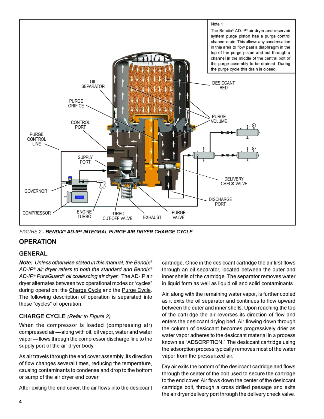
FIGURE 2 - BENDIX® AD-IP® INTEGRAL PURGE AIR DRYER CHARGE CYCLE
OPERATION
GENERAL
Note: Unless otherwise stated in this manual, the Bendix®
CHARGE CYCLE (Refer to Figure 2)
When the compressor is loaded (compressing air) compressed
As air travels through the end cover assembly, its direction of flow changes several times, reducing the temperature, causing contaminants to condense and drop to the bottom or sump of the air dryer end cover.
After exiting the end cover, the air flows into the desiccant
cartridge. Once in the desiccant cartridge the air first flows through an oil separator, located between the outer and inner shells of the cartridge. The separator removes water in liquid form as well as liquid oil and solid contaminants.
Air, along with the remaining water vapor, is further cooled as it exits the oil separator and continues to flow upward between the outer and inner shells. Upon reaching the top of the cartridge the air reverses its direction of flow and enters the desiccant drying bed. Air flowing down through the column of desiccant becomes progressively drier as water vapor adheres to the desiccant material in a process known as “ADSORPTION.” The desiccant cartridge using the adsorption process typically removes most of the water vapor from the pressurized air.
Dry air exits the bottom of the desiccant cartridge and flows through the center of the bolt used to secure the cartridge to the end cover. Air flows down the center of the desiccant cartridge bolt, through a cross drilled passage and exits the air dryer delivery port through the delivery check valve.
4