INSTALL CABLE
ASSEMBLY IN THIS AREA
32
33
DELIVERY
PORT
LOWER BRACKET |
|
|
| |
MOUNTING | 34 | 35 | INSERT CABLE | |
HOLES | ||||
| ||||
|
|
| ASSEMBLY IN UPPER |
| 31 | BRACKET WING HOLE AS |
| SHOWN | |
|
| |
8 | 9 |
|
|
| |
| 7 |
|
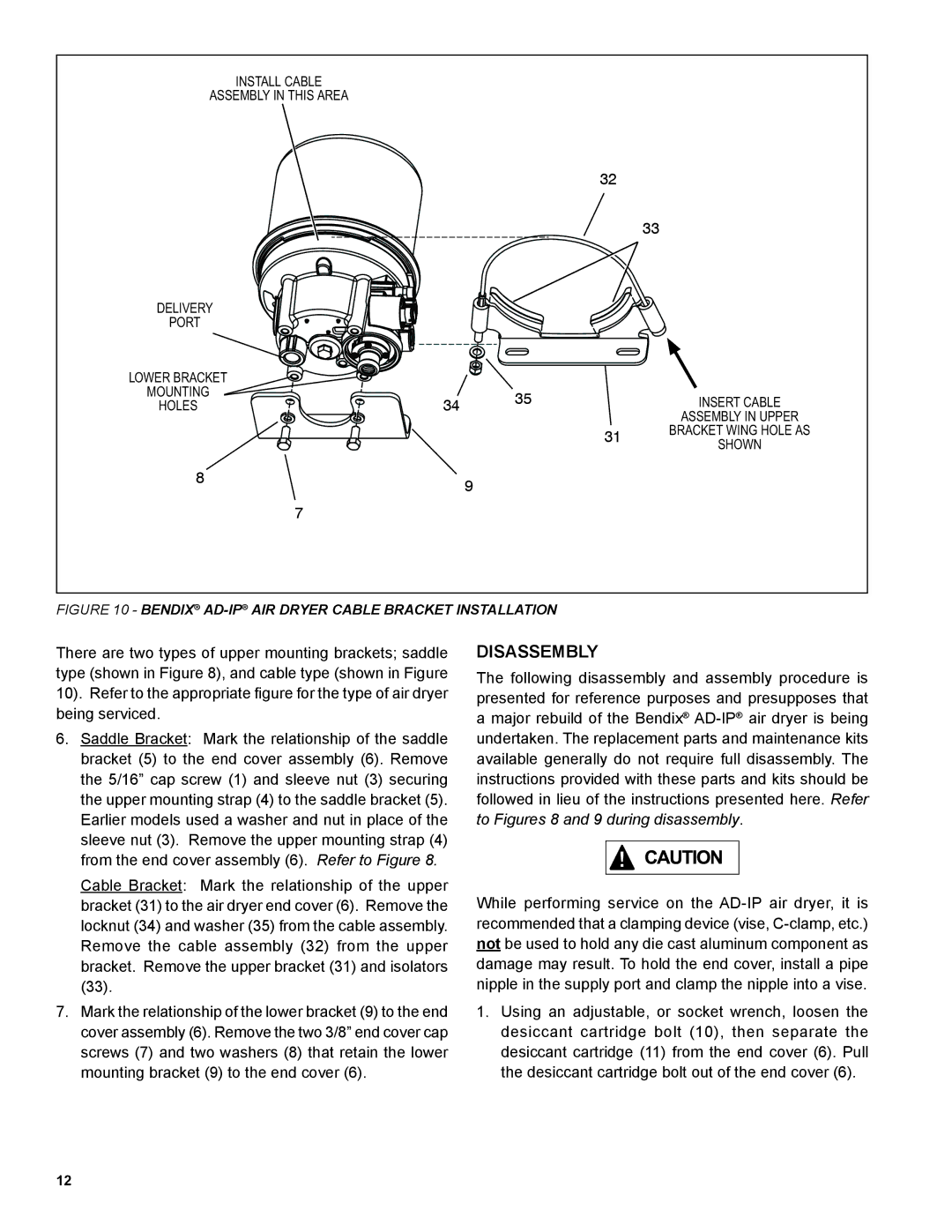
FIGURE 10 - BENDIX® AD-IP® AIR DRYER CABLE BRACKET INSTALLATION
There are two types of upper mounting brackets; saddle type (shown in Figure 8), and cable type (shown in Figure 10). Refer to the appropriate figure for the type of air dryer being serviced.
6.Saddle Bracket: Mark the relationship of the saddle bracket (5) to the end cover assembly (6). Remove the 5/16” cap screw (1) and sleeve nut (3) securing the upper mounting strap (4) to the saddle bracket (5). Earlier models used a washer and nut in place of the sleeve nut (3). Remove the upper mounting strap (4) from the end cover assembly (6). Refer to Figure 8.
Cable Bracket: Mark the relationship of the upper bracket (31) to the air dryer end cover (6). Remove the locknut (34) and washer (35) from the cable assembly. Remove the cable assembly (32) from the upper bracket. Remove the upper bracket (31) and isolators (33).
7.Mark the relationship of the lower bracket (9) to the end cover assembly (6). Remove the two 3/8” end cover cap screws (7) and two washers (8) that retain the lower mounting bracket (9) to the end cover (6).
DISASSEMBLY
The following disassembly and assembly procedure is presented for reference purposes and presupposes that a major rebuild of the Bendix®
While performing service on the
1.Using an adjustable, or socket wrench, loosen the desiccant cartridge bolt (10), then separate the desiccant cartridge (11) from the end cover (6). Pull the desiccant cartridge bolt out of the end cover (6).
12