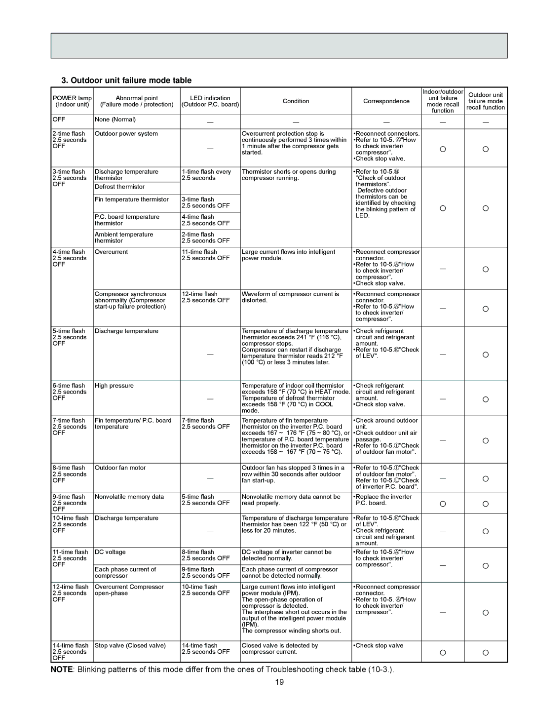
3. Outdoor unit failure mode table
POWER lamp | Abnormal point | LED indication |
(Indoor unit) | (Failure mode / protection) | (Outdoor P.C. board) |
|
|
|
Condition
Correspondence
Indoor/outdoor
unit failure
mode recall
function
Outdoor unit failure mode recall function
OFF | None (Normal) | — | — | — |
| — | — |
|
|
| |||||
|
|
|
|
|
|
| |
Outdoor power system |
| Overcurrent protection stop is | •Reconnect connectors. |
|
| ||
2.5 seconds |
|
| continuously performed 3 times within | •Refer to | "How | ○ | ○ |
OFF |
| — | 1 minute after the compressor gets | to check inverter/ | |||
|
| started. | compressor". |
| |||
|
|
|
| •Check stop valve. |
|
| |
|
|
|
|
|
|
|
|
Discharge temperature | Thermistor shorts or opens during | •Refer to |
|
|
| ||
2.5 seconds | thermistor | 2.5 seconds | compressor running. | "Check of outdoor |
|
| |
OFF | Defrost thermistor |
|
| thermistors". |
|
|
|
|
|
| Defective outdoor |
|
| ||
|
|
|
|
|
| ||
|
|
|
| thermistors can be |
|
| |
| Fin temperature thermistor |
| ○ | ○ | |||
|
| identified by checking | |||||
|
| 2.5 seconds OFF |
| ||||
|
|
| the blinking pattern of | ||||
|
|
|
| ||||
| P.C. board temperature |
| LED. |
|
|
| |
| thermistor | 2.5 seconds OFF |
|
|
|
|
|
|
|
|
|
|
|
|
|
| Ambient temperature |
|
|
|
|
| |
| thermistor | 2.5 seconds OFF |
|
|
|
|
|
|
|
|
|
|
|
| |
Overcurrent | Large current flows into intelligent | •Reconnect compressor |
|
| |||
2.5 seconds |
| 2.5 seconds OFF | power module. | connector. | "How |
| ○ |
OFF |
|
|
| •Refer to | — | ||
|
|
|
| to check inverter/ | |||
|
|
|
| compressor". |
|
|
|
|
|
|
| •Check stop valve. |
|
| |
| Compressor synchronous | Waveform of compressor current is | •Reconnect compressor |
|
| ||
| abnormality (Compressor | 2.5 seconds OFF | distorted. | connector. | "How |
| ○ |
|
|
| •Refer to | — | |||
|
|
|
| to check inverter/ | |||
|
|
|
| compressor". |
|
|
|
|
|
|
|
|
|
| |
Discharge temperature |
| Temperature of discharge temperature | •Check refrigerant |
|
| ||
2.5 seconds |
|
| thermistor exceeds 241 °F (116 °C), | circuit and refrigerant |
|
| |
OFF |
|
| compressor stops. | amount. | "Check |
| ○ |
|
| — | Compressor can restart if discharge | •Refer to | — | ||
|
| temperature thermistor reads 212 °F | of LEV". |
| |||
|
|
| (100 °C) or less 3 minutes later. |
|
|
|
|
|
|
|
|
|
|
| |
High pressure |
| Temperature of indoor coil thermistor | •Check refrigerant |
|
| ||
2.5 seconds |
| — | exceeds 158 °F (70 °C) in HEAT mode. | circuit and refrigerant | — | ○ | |
OFF |
| Temperature of defrost thermistor | amount. |
| |||
|
|
| exceeds 158 °F (70 °C) in COOL | •Check stop valve. |
| ||
|
|
| mode. |
|
|
|
|
Fin temperature/ P.C. board | Temperature of fin temperature | •Check around outdoor |
|
| |||
2.5 seconds | temperature | 2.5 seconds OFF | thermistor on the inverter P.C. board | unit. |
|
|
|
OFF |
|
| exceeds 167 ~ 176 °F (75 ~ 80 °C), or | •Check outdoor unit air | — | ○ | |
|
|
| temperature of P.C. board temperature | passage. | "Check | ||
|
|
| thermistor on the inverter P.C. board | •Refer to |
| ||
|
|
| exceeds 158 ~ 167 °F (70 ~ 75 °C). | of outdoor fan motor". |
|
| |
|
|
|
|
|
|
|
|
Outdoor fan motor |
| Outdoor fan has stopped 3 times in a | •Refer to | "Check |
| ○ | |
2.5 seconds |
| — | row within 30 seconds after outdoor | of outdoor fan motor". | — | ||
OFF |
| fan | Refer to | "Check | |||
|
|
|
| of inverter P.C. board". |
|
| |
Nonvolatile memory data | Nonvolatile memory data cannot be | •Replace the inverter | ○ | ○ | |||
OFF |
| 2.5 seconds OFF | read properly. | P.C. board. |
| ||
2.5 seconds |
|
|
|
| |||
Discharge temperature |
| Temperature of discharge temperature | •Refer to | "Check |
|
| |
2.5 seconds |
| — | thermistor has been 122 °F (50 °C) or | of LEV". |
| — | ○ |
OFF |
| less for 20 minutes. | •Check refrigerant | ||||
|
|
|
| circuit and refrigerant |
| ||
|
|
|
| amount. |
|
|
|
DC voltage | DC voltage of inverter cannot be | •Refer to | "How |
|
| ||
2.5 seconds |
| 2.5 seconds OFF | detected normally. | to check inverter/ |
| ○ | |
OFF |
|
|
| compressor". |
| — | |
Each phase current of | Each phase current of compressor |
| |||||
| compressor | 2.5 seconds OFF | cannot be detected normally. |
|
|
|
|
|
|
|
|
|
|
| |
Overcurrent Compressor | Large current flows into intelligent | •Reconnect compressor |
|
| |||
2.5 seconds | 2.5 seconds OFF | power module (IPM). | connector. | "How |
|
| |
OFF |
|
| The | •Refer to |
|
| |
|
|
| compressor is detected. | to check inverter/ | — | ○ | |
|
|
| The interphase short out occurs in the | compressor". |
| ||
|
|
| output of the intelligent power module |
|
|
| |
|
|
| (IPM). |
|
|
|
|
|
|
| The compressor winding shorts out. |
|
|
|
|
|
|
|
|
|
|
| |
Stop valve (Closed valve) | Closed valve is detected by | •Check stop valve | ○ | ○ | |||
OFF |
| 2.5 seconds OFF | compressor current. |
|
| ||
2.5 seconds |
|
|
|
|
| ||
NOTE: Blinking patterns of this mode differ from the ones of Troubleshooting check table
19