| OPERATING PROCEDURE |
| PHOTOS |
|
|
|
|
| ||
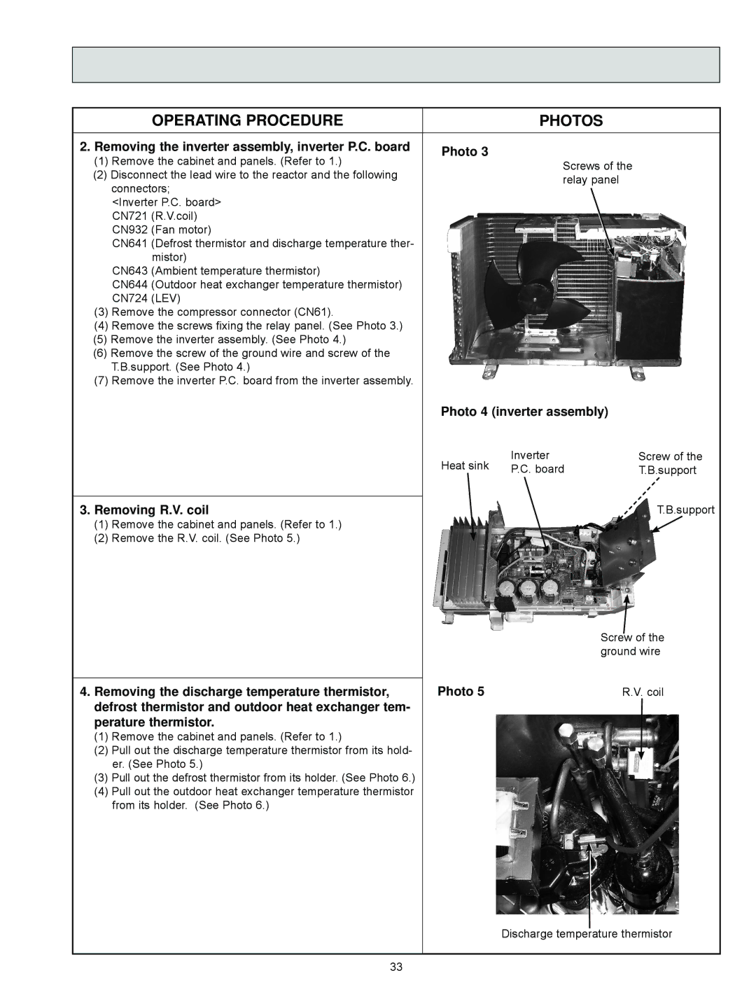
2. Removing the inverter assembly, inverter P.C. board | Photo 3 |
|
|
|
|
|
|
|
| |
(1) | Remove the cabinet and panels. (Refer to 1.) |
|
|
|
|
|
|
|
| |
|
| Screws of the |
|
|
|
|
| |||
(2) Disconnect the lead wire to the reactor and the following |
|
|
|
|
|
|
| |||
|
| relay panel |
|
|
|
|
| |||
| connectors; |
|
|
|
|
|
|
| ||
|
|
|
|
|
|
|
|
|
| |
|
|
|
|
|
|
|
|
|
| |
| <Inverter P.C. board> |
|
|
|
|
|
|
|
|
|
| CN721 (R.V.coil) |
|
|
|
|
|
|
|
|
|
| CN932 (Fan motor) |
|
|
|
|
|
|
|
|
|
| CN641 (Defrost thermistor and discharge temperature ther- |
|
|
|
|
|
|
|
|
|
| mistor) |
|
|
|
|
|
|
|
|
|
| CN643 (Ambient temperature thermistor) |
|
|
|
|
|
|
|
|
|
| CN644 (Outdoor heat exchanger temperature thermistor) |
|
|
|
|
|
|
|
|
|
| CN724 (LEV) |
|
|
|
|
|
|
|
|
|
(3) | Remove the compressor connector (CN61). |
|
|
|
|
|
|
|
|
|
(4) | Remove the screws fixing the relay panel. (See Photo 3.) |
|
|
|
|
|
|
|
|
|
(5) Remove the inverter assembly. (See Photo 4.) |
|
|
|
|
|
|
|
|
| |
(6) Remove the screw of the ground wire and screw of the |
|
|
|
|
|
|
|
|
| |
| T.B.support. (See Photo 4.) |
|
|
|
|
|
|
|
|
|
(7) | Remove the inverter P.C. board from the inverter assembly. |
|
|
|
|
|
|
|
|
|
|
| Photo 4 (inverter assembly) |
|
|
|
|
| |||
|
|
|
|
|
|
|
| |||
|
|
| Inverter | |||||||
|
| Heat sink |
| Screw of the | ||||||
|
| P.C. board |
| T.B.support |
| |||||
|
|
|
|
|
|
|
|
|
|
|
3. Removing R.V. coil |
|
|
|
|
|
|
|
|
| |
|
|
|
|
|
| T.B.support | ||||
(1) | Remove the cabinet and panels. (Refer to 1.) |
|
|
|
|
|
|
|
|
|
|
|
|
|
|
|
|
|
| ||
(2) | Remove the R.V. coil. (See Photo 5.) |
|
|
|
|
|
|
|
|
|
|
| Screw of the | ||
|
| ground wire | ||
| Photo 5 |
|
|
|
4. Removing the discharge temperature thermistor, |
|
|
| |
| R.V. coil | |||
defrost thermistor and outdoor heat exchanger tem- |
|
|
|
|
perature thermistor. |
|
|
|
|
(1)Remove the cabinet and panels. (Refer to 1.)
(2)Pull out the discharge temperature thermistor from its hold- er. (See Photo 5.)
(3)Pull out the defrost thermistor from its holder. (See Photo 6.)
(4)Pull out the outdoor heat exchanger temperature thermistor from its holder. (See Photo 6.)
Discharge temperature thermistor
33