10-5. TROUBLESHOOTING FLOW
POWER lamp flashes
Outdoor unit does not operate.
A How to check inverter/ compressor
Disconnect the connector (CN61) between compressor and the intelligent power module (IPM).
Check the voltage between terminals.
Are the voltages balanced?
Yes
Check the compressor.
![]()
![]() See
See ![]()
No | Replace the inverter P.C. board. |
|
See ![]()
B Check of open phase
●With the connector between the compressor and the intelligent power module disconnected, activate the inverter and check if the inverter is normal by measuring the balance of voltage between the terminals.
Output voltage 115 V
<< Operation method>>
Start cooling or heating operation by pressing EMERGENCY OPERATION switch on the indoor unit. (TEST RUN OPERATION : Refer to
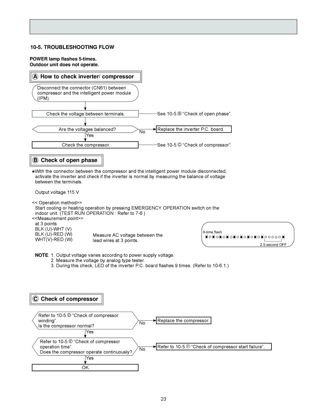
<<Measurement point>> at 3 points
BLK (U)-WHT (V)
BLK (U)-RED (W)
WHT(V)-RED (W)
NOTE: 1. Output voltage varies according to power supply voltage.
2.Measure the voltage by analog type tester.
3.During this check, LED of the inverter P.C. board flashes 9 times. (Refer to
C Check of compressor
Refer to ![]()
Is the compressor normal? Yes
Refer to ![]()
Does the compressor operate continuously? Yes
OK.
|
| Replace the compressor. | |
No | |||
| |||
|
| Refer to | |
No | |||
| |||
23