10-3. TROUBLESHOOTING CHECK TABLE
No. | Symptom | LED indication | Abnormal point/ | Condition | Correspondence | ||
Condition | |||||||
|
|
|
|
|
| ||
| Outdoor unit | Outdoor power sys- | Overcurrent protection stop is continuously performed 3 times | •Reconnect connector of compres- | |||
1 | does not oper- | 2.5 seconds | tem | within 1 minute after the compressor gets started, or failure of | sor. |
| |
ate. |
|
| restart of compressor has repeated 24 times. | •Refer to | |||
|
|
|
|
| verter/ compressor". | ||
|
|
|
|
| •Check stop valve. | ||
|
|
| Outdoor thermistors | Discharge temperature thermistor, fin temperature thermistor, | •Refer to | ||
2 |
|
|
| defrost thermistor, P.C. board temperature thermistor or ambi- | thermistors". |
| |
|
|
| ent temperature thermistor shorts or opens during compressor |
|
| ||
|
|
|
| running. |
|
| |
3 |
|
| Outdoor control sys- | Nonvolatile memory data cannot be read properly. | •Replace inverter P.C. board. | ||
|
| tem | (POWER lamp of the indoor unit lights up or flashes |
|
| ||
|
|
|
|
|
| ||
4 |
| Serial signal | The communication fails between the indoor and outdoor unit | •Refer to | "How to check | ||
| 2.5 seconds OFF |
| for 3 minutes. | miswiring and serial signal error. | |||
|
|
| |||||
5 |
| Stop valve/ | Closed valve is detected by compressor current. | •Check stop valve. | |||
| 2.5 seconds OFF | Closed valve |
|
|
| ||
|
|
|
|
| |||
|
| Outdoor unit | Outdoor unit is defective. | •Refer to | |||
6 |
| 2.5 seconds OFF | (Other abnormality) |
| detailed outdoor unit failure mode | ||
|
|
|
|
| recall function". |
| |
| 'Outdoor unit | Overcurrent protec- | Large current flows into intelligent power module. | •Reconnect connector of compres- | |||
7 | stops and | 2.5 seconds OFF | tion | When overcurrent protection occurs within 10 seconds after | sor. |
| |
restarts 3 min- |
|
| compressor starts, compressor restarts after 15 seconds. | •Refer to | |||
| utes later' is |
|
|
| verter/compressor". | ||
| repeated. |
|
|
| •Check stop valve. | ||
|
| Discharge tempera- | Temperature of discharge temperature thermistor exceeds 241 | •Check refrigerant circuit and refrig- | |||
8 |
| 2.5 seconds OFF | ture overheat protec- | °F (116 °C), compressor stops. Compressor can restart if dis- | erant amount. |
| |
|
| tion | charge temperature thermistor reads 212 °F (100 °C) or less 3 | •Refer to | "Check of LEV". | ||
|
|
|
| minutes later. |
|
| |
|
| Fin temperature /P.C. | Temperature of fin temperature thermistor on the heat sink ex- | •Check around outdoor unit. | |||
|
| 2.5 seconds OFF | board temperature | ceeds 167 ~ 176 °F (75 ~ 80 °C) or temperature of P.C. board | •Check outdoor unit air passage. | ||
9 |
|
| thermistor overheat | temperature thermistor on the inverter P.C. board exceeds 158 | •Refer to | ||
|
|
| protection | ~ 167 °F (70 ~ 75 °C). | fan motor". |
| |
|
|
|
|
|
| ||
10 |
| High pressure pro- | Indoor coil thermistor exceeds 158 °F (70 °C) in HEAT mode. | •Check refrigerant circuit and refrig- | |||
| 2.5 seconds OFF | tection | Defrost thermistor exceeds 158 °F (70 °C) in COOL mode. | erant amount. |
| ||
|
|
|
|
| •Check stop valve. | ||
|
| Compressor syn- | The waveform of compressor current is distorted. | •Reconnect connector of compres- | |||
11 |
| 2.5 seconds OFF | chronous abnormal- |
| sor. |
| |
|
| ity |
| •Refer to | |||
|
|
|
|
| verter/compressor". | ||
|
| Outdoor fan motor | Outdoor fan has stopped 3 times in a row within 30 seconds | •Refer to | |||
12 |
| 2.5 seconds OFF |
| after outdoor fan | fan motor. |
| |
|
|
|
| •Refer to | |||
|
|
|
|
| P.C. board. |
| |
13 |
| Each phase current | Each phase current of compressor cannot be detected nor- | •Refer to | "How to check in- | ||
| 2.5 seconds OFF | of compressor | mally | verter/compressor". | |||
|
| ||||||
14 |
| DC voltage | DC voltage of inverter cannot be detected normally. | •Refer to | "How to check in- | ||
| 2.5 seconds OFF |
|
| verter/compressor". | |||
|
|
|
| ||||
15 | Outdoor unit | Frequency drop by | Current from power outlet reaches the protection current, and | The unit is normal, but check the | |||
operates. | 2.5 seconds OFF | current protection | compressor frequency lowers. | following. |
| ||
|
|
|
|
| •Check if indoor filters are clogged. | ||
|
| Frequency drop by | Temperature of indoor coil thermistor exceeds 131 °F (55 °C) | ||||
|
| •Check if refrigerant is short. | |||||
|
| 2.5 seconds OFF | high pressure pro- | in HEAT mode, compressor frequency lowers. | |||
|
| •Check if indoor/outdoor unit air cir- | |||||
|
|
| tection |
| |||
16 |
|
|
| culation is short cycled. | |||
|
| Frequency drop by | Indoor coil thermistor reads 46 °F (8 °C) or less in COOL | ||||
|
|
|
|
| |||
|
|
| defrosting in COOL | mode, compressor frequency lowers. |
|
| |
|
|
| mode |
|
|
| |
|
| Frequency drop by | Temperature of discharge temperature thermistor exceeds 232 | •Check refrigerant circuit and refrig- | |||
17 |
| 2.5 seconds OFF | discharge tempera- | °F (111 °C), compressor frequency lowers. | erant amount. | "Check of LEV". | |
|
| ture protection |
| •Refer to | |||
|
|
|
|
| •Refer to | ||
|
|
|
|
| thermistors". |
| |
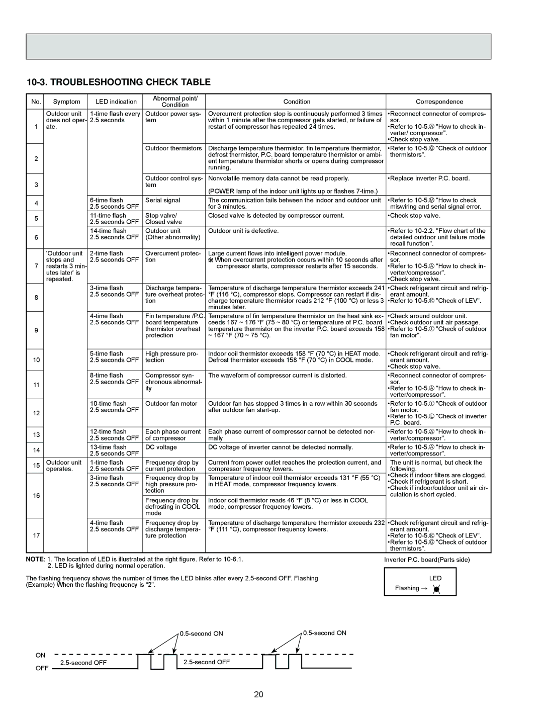
NOTE: 1. The location of LED is illustrated at the right figure. Refer to
The flashing frequency shows the number of times the LED blinks after every
Inverter P.C. board(Parts side)
LED
Flashing →
ON
OFF
20