Chapter 6: Operation
1 |
| 2 | |
| |||
3 | |||
1 | |||
|
| ||
4
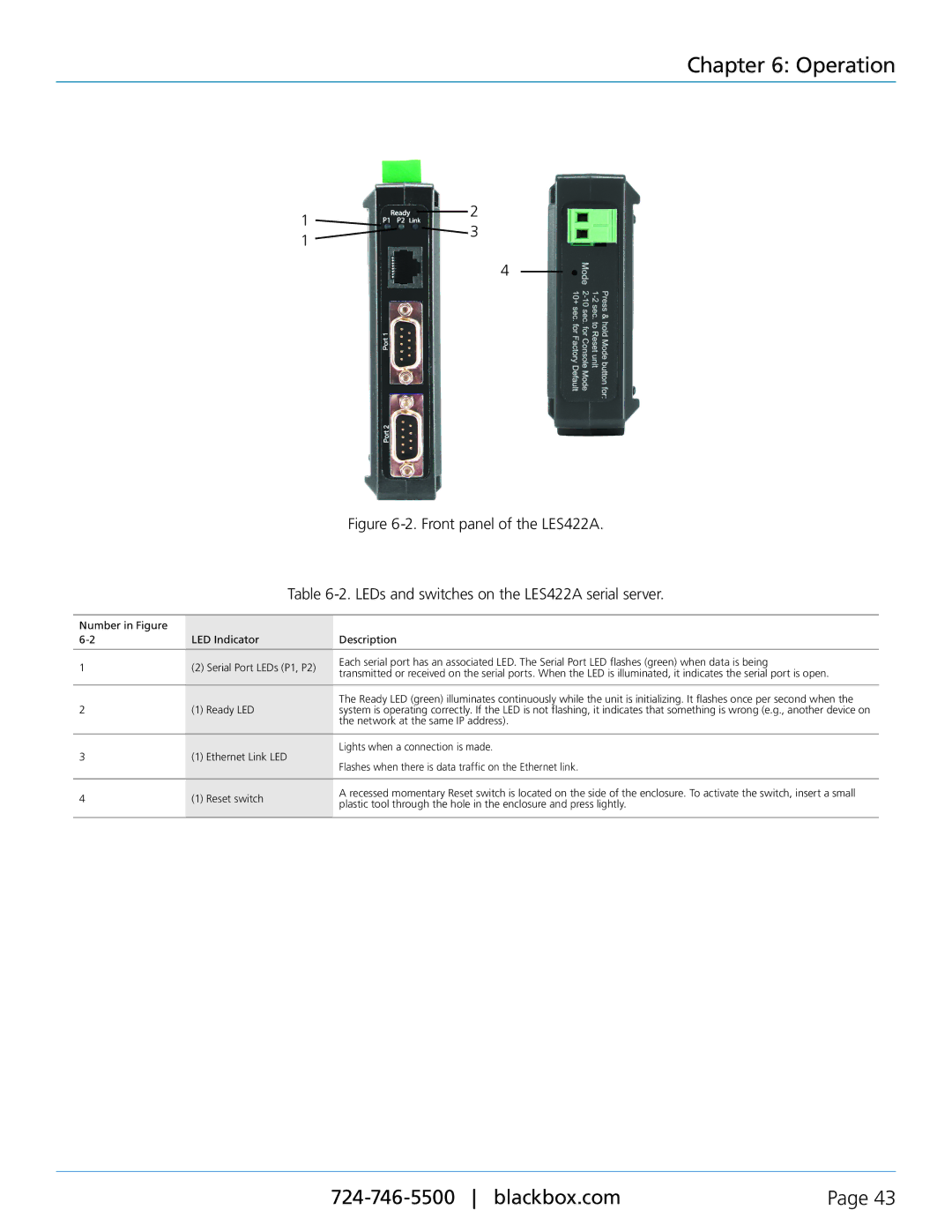
Figure 6-2. Front panel of the LES422A.
Table 6-2. LEDs and switches on the LES422A serial server.
Number in Figure |
|
|
| |
LED Indicator | Description | |||
|
|
|
| |
1 | (2) Serial Port LEDs (P1, P2) | Each serial port has an associated LED. The Serial Port LED flashes (green) when data is being | ||
transmitted or received on the serial ports. When the LED is illuminated, it indicates the serial port is open. | ||||
|
|
| ||
|
|
|
| |
|
|
| The Ready LED (green) illuminates continuously while the unit is initializing. It flashes once per second when the | |
2 | (1) | Ready LED | system is operating correctly. If the LED is not flashing, it indicates that something is wrong (e.g., another device on | |
|
|
| the network at the same IP address). | |
|
|
|
| |
3 | (1) | Ethernet Link LED | Lights when a connection is made. | |
Flashes when there is data traffic on the Ethernet link. | ||||
|
|
| ||
|
|
|
| |
4 | (1) | Reset switch | A recessed momentary Reset switch is located on the side of the enclosure. To activate the switch, insert a small | |
plastic tool through the hole in the enclosure and press lightly. | ||||
|
|
| ||
|
|
|
| |
Page 43 |