Chapter 6: Operation
4 | 3 | 4 | 5 | 5 |
3
2
1 ![]()
55
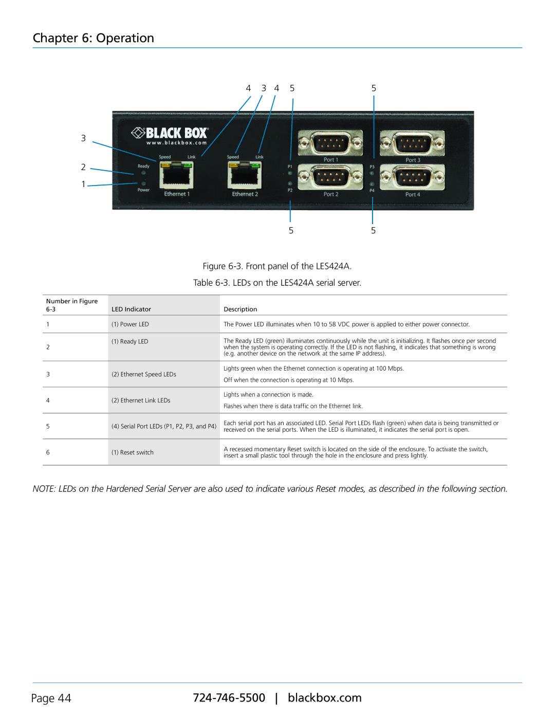
Figure 6-3. Front panel of the LES424A.
Table 6-3. LEDs on the LES424A serial server.
Number in Figure |
|
| |
LED Indicator | Description | ||
|
|
| |
1 | (1) Power LED | The Power LED illuminates when 10 to 58 VDC power is applied to either power connector. | |
|
|
| |
2 | (1) Ready LED | The Ready LED (green) illuminates continuously while the unit is initializing. It flashes once per second | |
| when the system is operating correctly. If the LED is not flashing, it indicates that something is wrong | ||
|
| (e.g. another device on the network at the same IP address). | |
|
|
| |
3 | (2) Ethernet Speed LEDs | Lights green when the Ethernet connection is operating at 100 Mbps. | |
Off when the connection is operating at 10 Mbps. | |||
|
| ||
|
|
| |
4 | (2) Ethernet Link LEDs | Lights when a connection is made. | |
Flashes when there is data traffic on the Ethernet link. | |||
|
| ||
|
|
| |
5 | (4) Serial Port LEDs (P1, P2, P3, and P4) | Each serial port has an associated LED. Serial Port LEDs flash (green) when data is being transmitted or | |
received on the serial ports. When the LED is illuminated, it indicates the serial port is open. | |||
|
| ||
|
|
| |
6 | (1) Reset switch | A recessed momentary Reset switch is located on the side of the enclosure. To activate the switch, | |
insert a small plastic tool through the hole in the enclosure and press lightly. | |||
|
| ||
|
|
|
NOTE: LEDs on the Hardened Serial Server are also used to indicate various Reset modes, as described in the following section.
Page 44 |