Black Box ServSwitch Wizard VGA (USB), KV3004A, KV3204A, KV3404A, KV3304A specifications
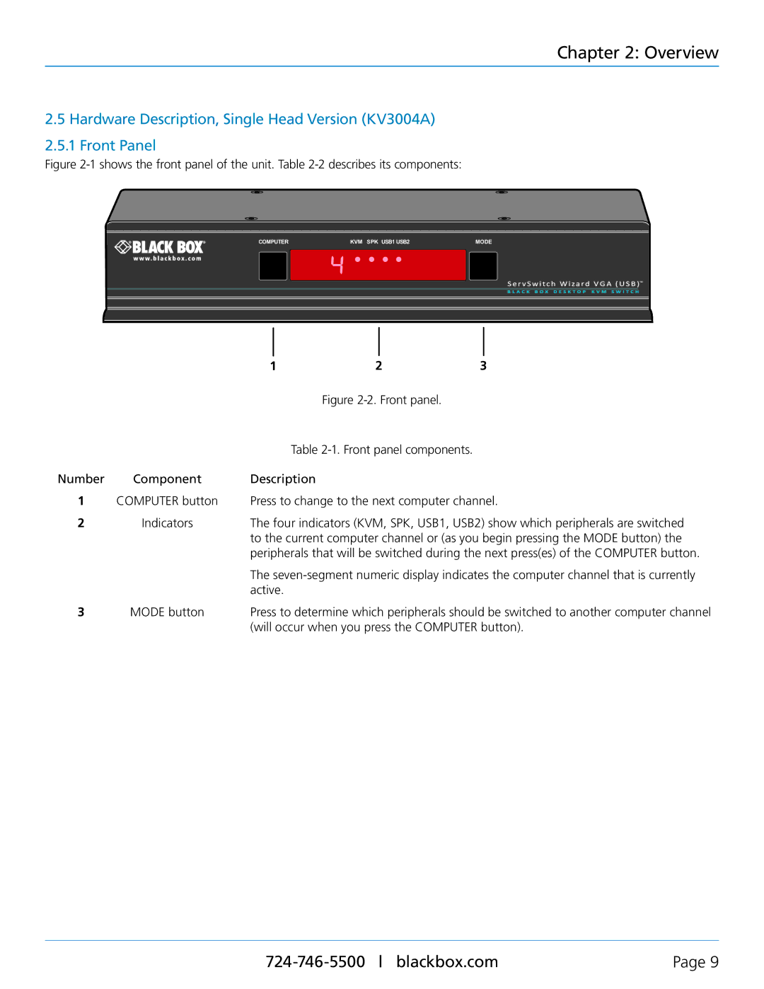
The Black Box KV series of KVM (Keyboard, Video, Mouse) switches, including the KV3404A, KV3204A, KV3304A, and KV3004A, offer a robust solution for managing multiple computers from a single workstation. These devices are designed for efficiency, reliability, and user-friendly operation, catering to the needs of IT professionals across various industries.The KV3404A KVM switch is capable of supporting up to four servers and features high-resolution VGA video output. It employs USB technology for keyboard and mouse connectivity, ensuring broad compatibility with various operating systems. This switch enables users to quickly switch between connected servers using a simple push-button interface or keyboard shortcuts, enhancing workflow and saving time.
The KV3204A offers similar functionality but adds the convenience of a built-in OSD (On-Screen Display), which provides an intuitive graphical interface for managing the connected devices. The OSD allows users to easily identify and switch between servers using an on-screen menu, streamlining operations in environments with multiple systems.
The Black Box ServSwitch Wizard VGA (USB) is known for its advanced video enhancement technology, providing superior image quality and extended distance support. It can transmit video signals up to 65 meters, making it suitable for large areas where the servers may be located far from the workstation. Additionally, this model is compatible with various video resolutions, ensuring high-definition performance across all connected devices.
The KV3304A and KV3004A models cater to different user needs, with the KV3304A supporting video resolutions up to 1920 x 1080 pixels. Meanwhile, the KV3004A focuses on essential KVM functionality, making it an economical choice for users who require basic switching capabilities without additional features.
In terms of security, these KVM switches are equipped with features like hot plugging and keyboard and mouse emulation, ensuring a seamless user experience. With support for multiple operating systems, including Windows and Linux, the KV series presents a versatile solution for businesses looking to optimize their IT management.
Overall, the Black Box KV series provides a comprehensive, user-centric approach to KVM switching. With advanced features, reliable performance, and excellent compatibility, these devices are ideal for data centers, server rooms, and any environment where efficient server management is a priority.

