SERVSWITCH™ USB AND USB PLUS
2.3 The ServSwitch USB Illustrated
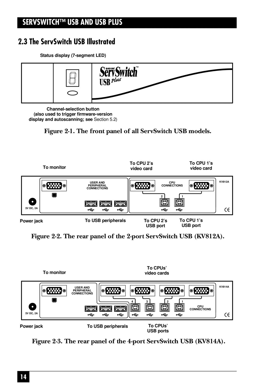
Status display (7-segment LED)
display and autoscanning; see | Section 5.2) |
Figure 2-1. The front panel of all ServSwitch USB models.
To monitor | To CPU 2’s | To CPU 1’s |
video card | video card |
USER AND | CPU | KV812A |
PERIPHERAL | CONNECTIONS |
|
CONNECTIONS |
|
|
| 2 | 1 |
5V DC, 2A |
|
|
Power jack | To USB peripherals | To CPU 2’s | To CPU 1’s |
|
| USB port | USB port |
Figure 2-2. The rear panel of the 2-port ServSwitch USB (KV812A).
To monitor | To CPUs’ |
video cards |
USER AND |
|
| KV814A |
PERIPHERAL |
|
|
|
CONNECTIONS |
|
|
|
4 | 3 | 2 | 1 |
|
|
| CPU |
|
|
| CONNECTIONS |
5V DC, 2A |
|
|
|
Power jack | To USB peripherals | To CPUs’ |
|
| USB ports |
Figure 2-3. The rear panel of the 4-port ServSwitch USB (KV814A).
14