SERVSWITCH™ USB AND USB PLUS
5.3 Interpreting the Status Display During Normal Operation
The ServSwitch USB’s
When you change CPU channels, this display will flash as shown in the second illustration below, more and more quickly, until the USB “enumeration” process is complete (see Section 3.1); until the display stops flashing, the channel cannot be changed again.
If you hold in the Switch’s
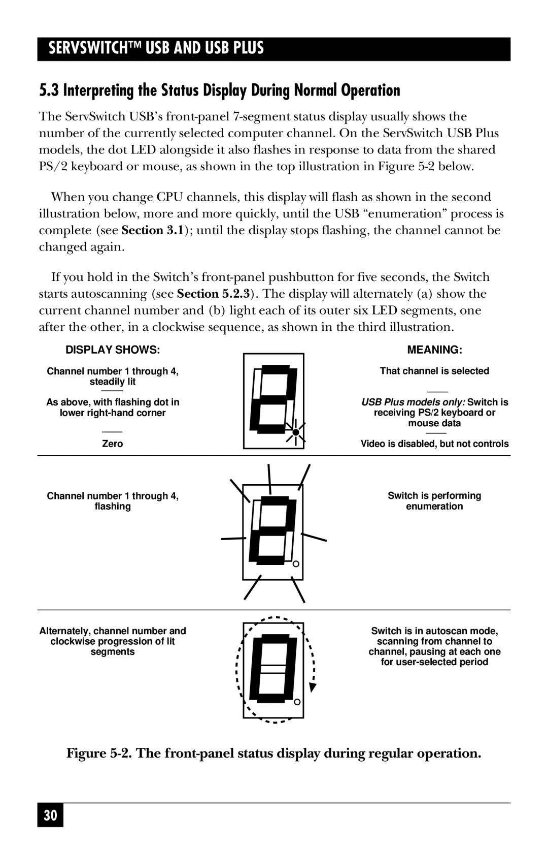
DISPLAY SHOWS: | MEANING: |
| ||||
Channel number 1 through 4, | That channel is selected |
| ||||
steadily lit |
|
|
|
| ||
|
|
|
|
| ||
As above, with flashing dot in | USB Plus models only: | Switch is | ||||
lower | receiving PS/2 keyboard or | |||||
|
|
| mouse data |
| ||
|
|
|
|
| ||
| Zero | Video is disabled, but not controls | ||||
|
|
|
|
|
|
|
Channel number 1 through 4, flashing
Switch is performing enumeration
Alternately, channel number and clockwise progression of lit
segments
Switch is in autoscan mode, scanning from channel to
channel, pausing at each one for
Figure 5-2. The front-panel status display during regular operation.
30