Router Table Assembly
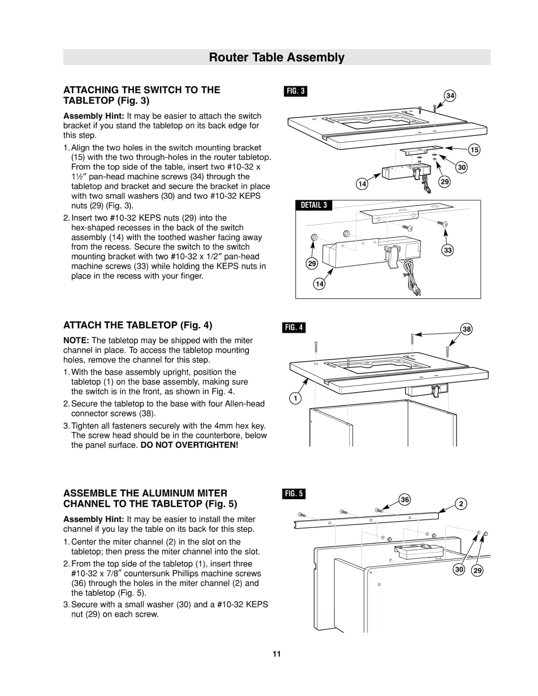
ATTACHING THE SWITCH TO THE TABLETOP (Fig. 3)
Assembly Hint: It may be easier to attach the switch bracket if you stand the tabletop on its back edge for this step.
1.Align the two holes in the switch mounting bracket (15) with the two
From the top side of the table, insert two
2.Insert two
from the recess. Secure the switch to the switch mounting bracket with two
ATTACH THE TABLETOP (Fig. 4)
NOTE: The tabletop may be shipped with the miter channel in place. To access the tabletop mounting holes, remove the channel for this step.
1.With the base assembly upright, position the tabletop (1) on the base assembly, making sure the switch is in the front, as shown in Fig. 4.
2.Secure the tabletop to the base with four
3.Tighten all fasteners securely with the 4mm hex key. The screw head should be in the counterbore, below the panel surface. DO NOT OVERTIGHTEN!
FIG. 3 |
| 34 |
|
| |
|
| 15 |
|
| 30 |
| 14 | 29 |
|
| |
DETAIL 3 |
|
|
|
| 33 |
29 |
|
|
14 |
|
|
FIG. 4 |
| 38 |
1 |
|
|
ASSEMBLE THE ALUMINUM MITER | FIG. 5 |
|
CHANNEL TO THE TABLETOP (Fig. 5) | 36 | 2 |
|
Assembly Hint: It may be easier to install the miter channel if you lay the table on its back for this step.
1. Center the miter channel (2) in the slot on the tabletop; then press the miter channel into the slot.
2. From the top side of the tabletop (1), insert three
30 | 29 | |
|
(36) through the holes in the miter channel (2) and the tabletop (Fig. 5).
3.Secure with a small washer (30) and a
11
