Features (Fig. 1) |
|
|
|
|
|
|
|
|
|
|
|
|
|
|
| |
|
|
|
|
| A |
| ||||||||||
|
|
|
|
|
|
|
| |||||||||
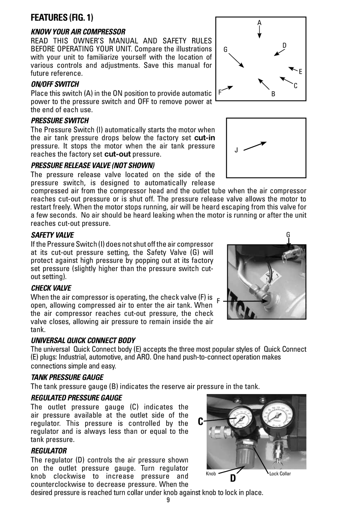
Know Your Air Compressor |
|
|
|
|
|
|
|
|
|
|
|
|
|
|
| |
|
|
|
|
|
|
|
|
|
|
|
|
|
| |||
READ THIS OWNER’S MANUAL AND SAFETY RULES |
|
|
|
|
|
|
|
|
|
|
|
|
|
|
| |
|
|
|
|
|
|
|
| d |
|
|
|
|
| |||
BEFORE OPERATING YOUR UNIT. Compare the illustrations |
|
|
|
|
|
|
|
|
|
|
|
| ||||
|
| G |
|
|
|
|
| |||||||||
|
|
|
|
|
|
|
|
|
|
|
|
| ||||
with your unit to familiarize yourself with the location of |
|
|
|
|
|
|
|
|
|
|
|
|
|
|
|
|
|
|
|
|
|
|
|
|
|
|
|
|
|
|
| ||
various controls and adjustments. Save this manual for |
|
|
|
|
|
|
|
|
|
|
|
|
|
|
| |
future reference. |
|
|
|
|
|
|
|
|
|
|
|
| E |
| ||
On/Off Switch |
|
|
|
|
|
|
|
|
|
|
|
|
|
| ||
F |
|
|
|
|
|
|
|
|
|
| c |
| ||||
Place this switch (A) in the ON position to provide automatic |
|
|
|
|
|
| B |
|
|
|
|
|
|
| ||
|
|
|
|
|
|
|
|
|
|
|
|
| ||||
power to the pressure switch and OFF to remove power at |
|
|
|
|
|
|
|
|
|
|
|
|
|
|
| |
|
|
|
|
|
|
|
|
|
|
|
|
|
| |||
|
|
|
|
|
|
|
|
|
|
|
|
|
|
| ||
the end of each use. |
|
|
|
|
|
|
|
|
|
|
|
|
|
| ||
Pressure Switch |
|
|
|
|
|
|
|
|
|
|
|
|
|
| ||
|
|
|
|
|
|
|
|
|
|
|
|
|
| |||
The Pressure Switch (I) automatically starts the motor when |
|
|
|
|
|
|
|
|
|
|
|
|
|
| ||
the air tank pressure drops below the factory set |
|
|
|
|
|
|
|
|
|
|
|
|
|
| ||
pressure. It stops the motor when the air tank pressure |
|
|
|
|
|
|
|
|
|
|
|
|
|
| ||
|
|
| J |
|
|
|
|
|
|
|
|
|
| |||
reaches the factory set |
|
|
|
|
| |||||||||||
|
|
|
|
|
|
|
|
|
|
|
|
|
| |||
Pressure Release Valve (NOT SHOWN)
The pressure release valve located on the side of the pressure switch, is designed to automatically release
compressed air from the compressor head and the outlet tube when the air compressor reaches
Safety Valve | G |
If the Pressure Switch (I) does not shut off the air compressor at its
Check Valve
When the air compressor is operating, the check valve (F) is f open, allowing compressed air to enter the air tank. When the air compressor reaches
Universal Quick Connect BodY
The universal Quick Connect body (E) accepts the three most popular styles of Quick Connect
(E)plugs: Industrial, automotive, and ARO. One hand
Tank Pressure Gauge
The tank pressure gauge (B) indicates the reserve air pressure in the tank.
regulated Pressure Gauge
The outlet pressure gauge (C) indicates the air pressure available at the outlet side of the
regulator. This pressure is controlled by the C![]() regulator and is always less than or equal to the
regulator and is always less than or equal to the
tank pressure.
Regulator |
|
|
| |
The regulator (D) controls the air pressure shown |
|
|
| |
on the outlet pressure gauge. Turn regulator | Knob |
| Lock Collar | |
knob clockwise to increase pressure and |
| |||
D | ||||
|
| |||
counterclockwise to decrease pressure. When the |
|
|
| |
|
|
|
desired pressure is reached turn collar under knob against knob to lock in place.
9