SERVICE PROCEDURE D24-I
Thermostat Circuit Testing
![]()
![]()
![]()
![]() DANGER
DANGER
120 volt exposure. To avoid personal injury, use caution while performing this procedure.
CAUTION |
Be Careful When Making Voltage |
Measurements or Jumping Terminals |
Not to Damage or Deform Connectors or |
Connector Pins. |
This procedure assumes the flue damper is in working order. Be sure damper opens under its own power when the thermostat circuit is
Condition: Water Heater Not Operating
Display shows error code “31” (Upper Sensor
Readings Faulty) or error code “32” (Lower Sensor
Readings Faulty)
Unplug or disconnect electrical power to the water heater
Check continuity of wire harness to affected sensor. Measurement of ohmeter should be close to 0 ohms. Replace wire harness if high resistance is measured (over 0.5 ohms) Check wires for intermittent connections, shorts, frayed insulation. Replace if necessary
(see photo 8)
If wire harness checks out O.K.check resistance of sensor. Refer to section on Sensor Resistance Testing. If sensor resistance is not near the values shown in the table, then replace upper or lower sensor as indicated by error code number.
Turn power on to water heater.
Run water heater through heating cycle and verify proper operation.
Sensor temperature can be viewed when burner shuts off (see
section on viewing the display in “Service Mode”.
Condition: Water Heater Not Operating
Display shows error code “65”
High Water Temperature (over 200 deg. F)
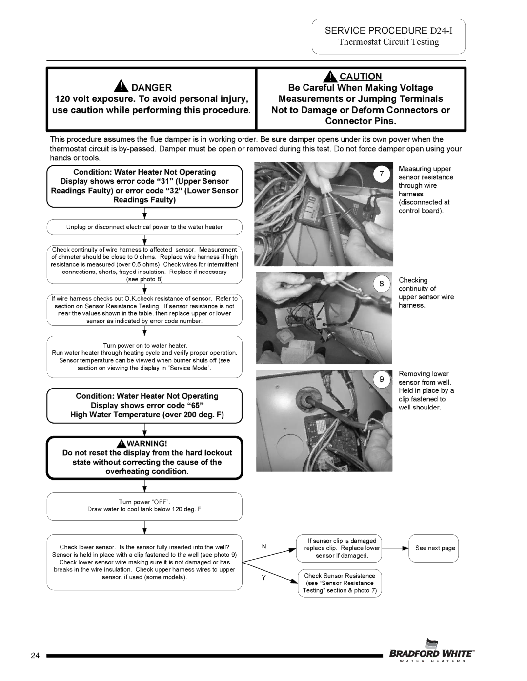
Measuring upper
7 sensor resistance through wire harness (disconnected at control board).
8Checking continuity of upper sensor wire harness.
Removing lower
9 sensor from well. Held in place by a clip fastened to well shoulder.
WARNING! |
Do not reset the display from the hard lockout |
state without correcting the cause of the |
overheating condition. |
Turn power “OFF”.
Draw water to cool tank below 120 deg. F
Check lower sensor. Is the sensor fully inserted into the well? | N |
Sensor is held in place with a clip fastened to the well (see photo 9) |
|
Check lower sensor wire making sure it is not damaged or has |
|
breaks in the wire insulation. Check upper harness wires to upper |
|
sensor, if used (some models). | Y |
| Page 24 |
If sensor clip is damaged
replace clip. Replace lower ![]() See next page sensor if damaged.
See next page sensor if damaged.
Check Sensor Resistance (see “Sensor Resistance Testing” section & photo 7)
24