SERVICE PROCEDURE D24-III
Main Burner Operation Testing
![]()
![]()
![]()
![]() DANGER
DANGER
120 volt exposure. To avoid personal injury, use caution while performing this procedure.
CAUTION |
Be Careful When Making Voltage |
Measurements or Jumping Terminals |
Not to Damage or Deform Connectors or |
Connector Pins. |
|
|
|
|
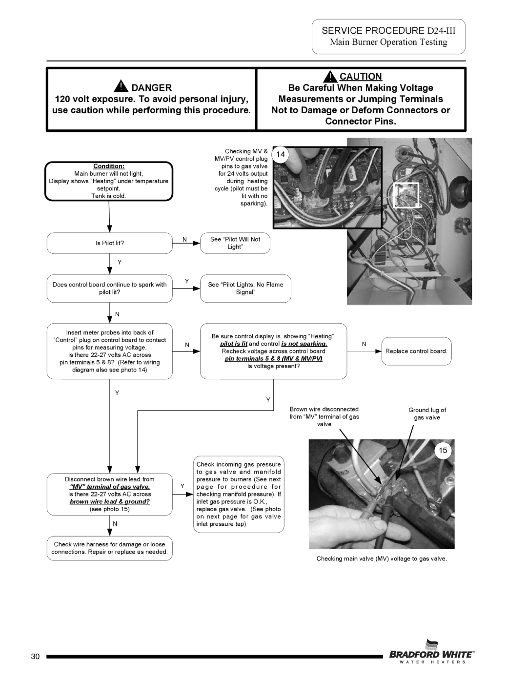
| Checking MV & |
| Condition: |
|
| MV/PV control plug | |
|
| pins to gas valve | |||
Main burner will not light, |
| for 24 volts output | |||
Display shows “Heating” under temperature |
| during heating | |||
| setpoint. |
| cycle (pilot must be | ||
Tank is cold. |
| lit with no | |||
|
|
|
|
| sparking). |
| Is Pilot lit? | N | See “Pilot Will Not | ||
|
| Light” | |||
|
|
|
|
| |
|
| Y |
|
| |
|
|
|
| ||
|
|
|
|
|
|
114
Does control board continue to spark with | Y | See “Pilot Lights, No Flame | |
| |||
pilot lit? |
| Signal” | |
| N |
|
|
|
|
| |
Insert meter probes into back of |
| Be sure control display is showing “Heating”, |
| |||||||||
“Control” plug on control board to contact |
|
| ||||||||||
N |
| pilot is lit and control is not sparking. | N | |||||||||
pins for measuring voltage. |
| |||||||||||
|
|
|
|
|
|
|
|
|
|
| ||
|
| Recheck voltage across control board |
|
| ||||||||
Is there |
|
|
|
| ||||||||
|
|
| pin terminals 5 & 8 (MV & MV/PV) |
| ||||||||
pin terminals 5 & 8? (Refer to wiring |
|
|
|
| ||||||||
|
|
|
| Is voltage present? |
|
| ||||||
diagram also see photo 14) |
|
|
|
|
| |||||||
|
|
|
|
|
|
|
|
|
|
| ||
Y |
|
|
|
| Y |
|
|
|
|
|
| |
|
|
|
|
|
|
|
|
|
| |||
|
|
|
|
|
|
|
|
| ||||
|
|
|
|
|
|
|
| Brown wire disconnected |
| |||
|
|
|
|
|
|
|
|
| ||||
|
|
|
|
|
|
|
| from “MV” terminal of gas |
| |||
|
|
|
|
|
|
|
| valve |
| |||
Replace control board.
Ground lug of
gas valve
|
|
|
|
|
| Check incoming gas pressure |
|
|
|
|
|
| to gas valve and manifold |
Disconnect brown wire lead from | Y | pressure to burners (See next | ||||
| “MV” terminal of gas valve. |
| p a g e f o r p r o c e d u r e f o r | |||
Is there |
| checking manifold pressure). If | ||||
| ||||||
| brown wire lead & ground? |
|
| inlet gas pressure is O.K., | ||
| (see photo 15) |
| replace gas valve. (See photo | |||
|
| N |
| on next page for gas valve | ||
|
|
| ||||
|
|
| inlet pressure tap) | |||
Check wire harness for damage or loose |
|
| ||||
connections. Repair or replace as needed. |
|
| ||||
15
Checking main valve (MV) voltage to gas valve.
Page 30
30