SERVICE PROCEDURE D24-II
Pilot Operation Testing
![]()
![]()
![]()
![]() DANGER
DANGER
120 volt exposure. To avoid personal injury, use caution while performing this procedure.
CAUTION |
Be Careful When Making Voltage |
Measurements or Jumping Terminals |
Not to Damage or Deform Connectors or |
Connector Pins. |
Condition:
Pilot will not light or stay lit,
Error codes 62, or 63 shown on Water
Heater Display
Reset control by pressing the lower right button under “reset” on the display for 3 seconds. Does control board start ignition sequence and start sparking (sparking noise at pilot or at board)
Y
Is there spark at the pilot?
Y
Is there
(see photo 13)
Y
Is there
wire leads
“MV/PV” & “PV” (yellow & red wires)
at Gas Valve? (see photo 12)
N
Check wire harness for damage or loose connections. Repair or replace as needed.
Turn on power to the water heater
and verify proper operation
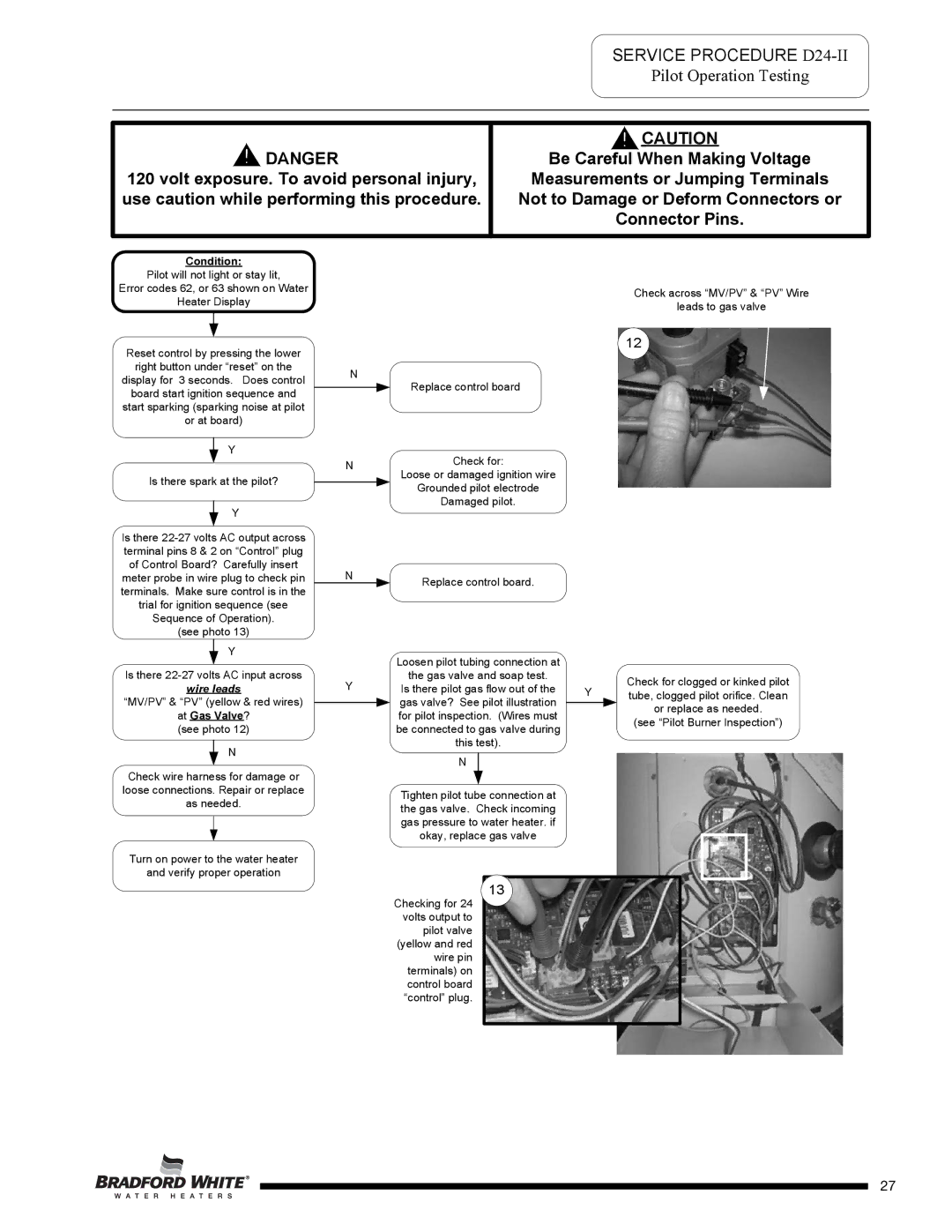
Check across “MV/PV” & “PV” Wire
leads to gas valve
12
N
Replace control board
N | Check for: | |
Loose or damaged ignition wire | ||
| ||
| Grounded pilot electrode | |
| Damaged pilot. |
N | Replace control board. |
|
| Loosen pilot tubing connection at |
|
| ||
Y | the gas valve and soap test. |
| Check for clogged or kinked pilot | ||
Is there pilot gas flow out of the | Y | ||||
tube, clogged pilot orifice. Clean | |||||
| gas valve? See pilot illustration | ||||
|
| or replace as needed. | |||
| for pilot inspection. (Wires must |
| |||
|
| (see “Pilot Burner Inspection”) | |||
| be connected to gas valve during |
| |||
|
|
| |||
| this test). |
|
| ||
|
|
|
| ||
| N |
|
|
| |
| Tighten pilot tube connection at |
|
| ||
| the gas valve. Check incoming |
|
| ||
| gas pressure to water heater. if |
|
| ||
| okay, replace gas valve |
|
| ||
131
Checking for 24 volts output to pilot valve (yellow and red wire pin terminals) on control board “control” plug.
Page 27
27