TM
SLE100 Installation Manual
Figure 3-12: RSL and Quality Test Cable Connection Point
The voltmeter should be set to DC voltage and the x 20 setting. The expected RSL level is dependent on the distance between the two radio terminals. A chart is provided in Appendix B.
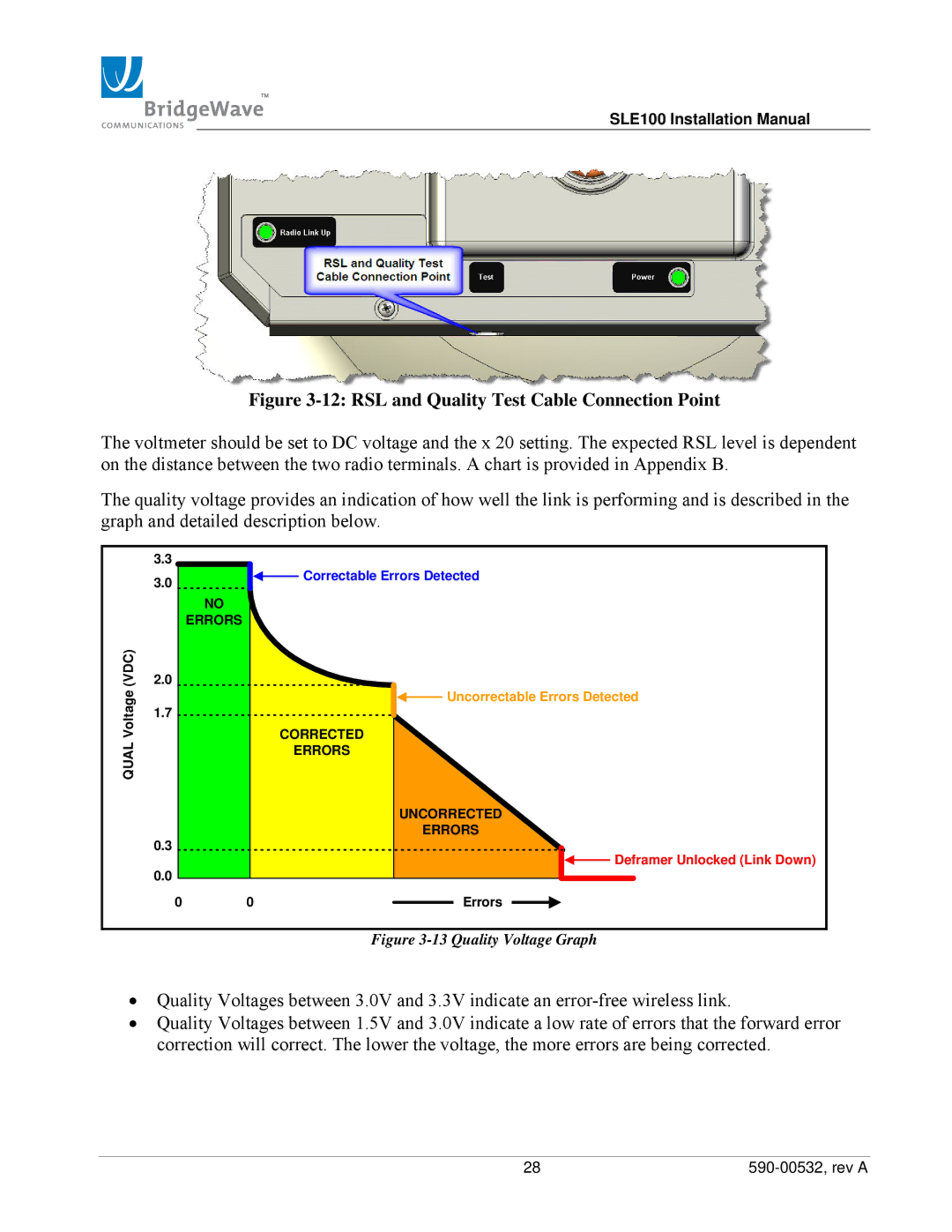
The quality voltage provides an indication of how well the link is performing and is described in the graph and detailed description below.
QUAL Voltage (VDC)
3.3
3.0![]()
![]() Correctable Errors Detected
Correctable Errors Detected
NO
ERRORS
2.0
![]() Uncorrectable Errors Detected
Uncorrectable Errors Detected
1.7
CORRECTED
ERRORS
UNCORRECTED
ERRORS
0.3
![]() Deframer Unlocked (Link Down)
Deframer Unlocked (Link Down)
0.0
0 | 0 |
| Errors |
|
Figure 3-13 Quality Voltage Graph
•Quality Voltages between 3.0V and 3.3V indicate an
•Quality Voltages between 1.5V and 3.0V indicate a low rate of errors that the forward error correction will correct. The lower the voltage, the more errors are being corrected.
28 |