TM
SLE100 Installation Manual
2 Site Planning
2.1 General
Before the start of an installation a survey should be conducted of the proposed area of the site(s). The survey personnel should be fully familiar with the details required to install the BridgeWave radio system.
2.2 Equipment Checklist
The survey team will need the following equipment:
•Tape Measure
•Site Survey Report Form
2.3Line of Sight (LOS)
BridgeWave Wireless links require
The planning should include an investigation into future building plans that could block the LOS path, and other
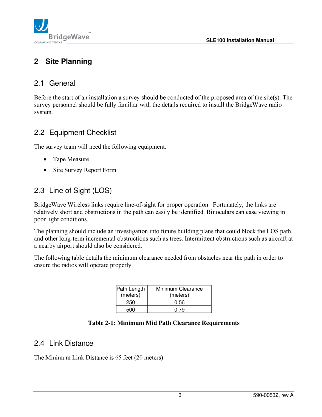
The following table details the minimum clearance needed from obstacles near the path in order to ensure the radios will operate properly.
Path Length | Minimum Clearance |
(meters) | (meters) |
250 | 0.56 |
500 | 0.79 |
Table
2.4 Link Distance
The Minimum Link Distance is 65 feet (20 meters)
3 |