TM
SLE100 Installation Manual
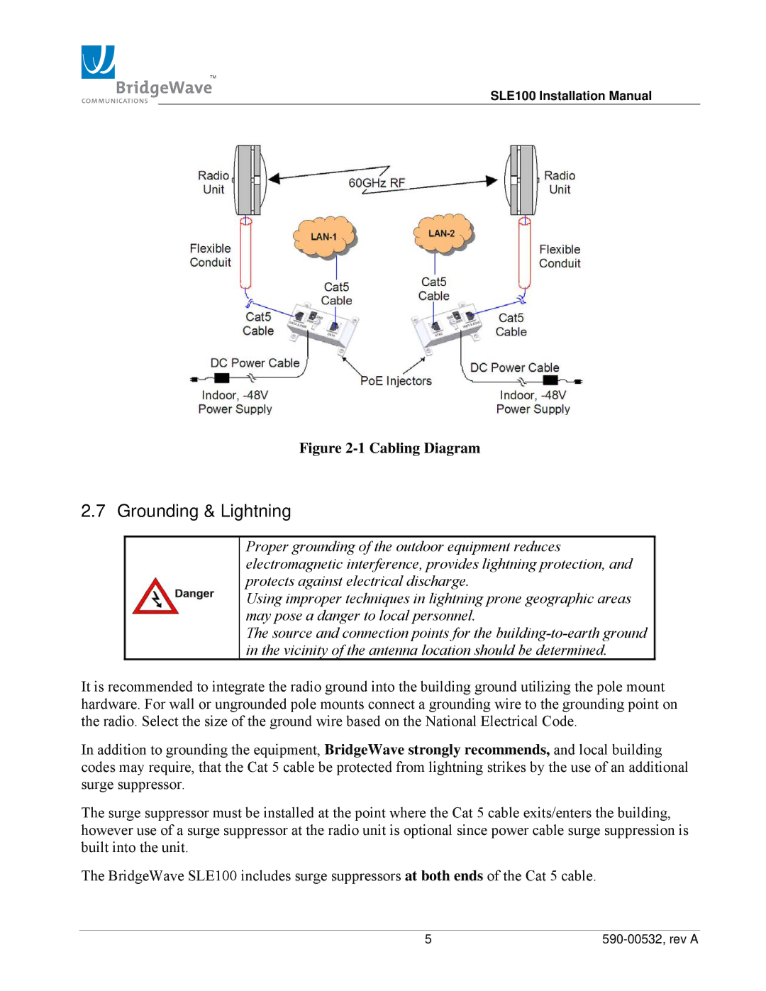
Figure 2-1 Cabling Diagram
2.7 Grounding & Lightning
Proper grounding of the outdoor equipment reduces electromagnetic interference, provides lightning protection, and protects against electrical discharge.
Using improper techniques in lightning prone geographic areas may pose a danger to local personnel.
The source and connection points for the
It is recommended to integrate the radio ground into the building ground utilizing the pole mount hardware. For wall or ungrounded pole mounts connect a grounding wire to the grounding point on the radio. Select the size of the ground wire based on the National Electrical Code.
In addition to grounding the equipment, BridgeWave strongly recommends, and local building codes may require, that the Cat 5 cable be protected from lightning strikes by the use of an additional surge suppressor.
The surge suppressor must be installed at the point where the Cat 5 cable exits/enters the building, however use of a surge suppressor at the radio unit is optional since power cable surge suppression is built into the unit.
The BridgeWave SLE100 includes surge suppressors at both ends of the Cat 5 cable.
5 |