TM
SLE100 Installation Manual
These instructions can also be found on the radio’s back cover.
3.9 QUAL & RSL Test Cable
The alignment procedure is optimized through the use of the provided test cable. The test cable is designed for use with a digital voltmeter (not provided) to read the Link Quality and Receive Signal Level (RSL) voltage generated by the radio’s receiver.
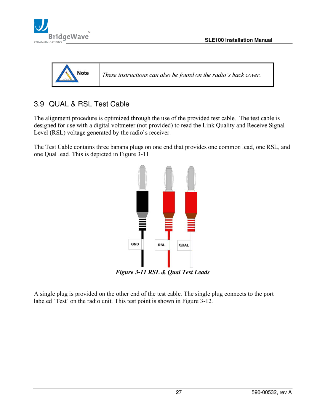
The Test Cable contains three banana plugs on one end that provides one common lead, one RSL, and one Qual lead. This is depicted in Figure
Figure 3-11 RSL & Qual Test Leads
A single plug is provided on the other end of the test cable. The single plug connects to the port labeled ‘Test’ on the radio unit. This test point is shown in Figure
27 |