C.Condensate Trap Field Drain Attachment

Refer to Condensate Drain section for recommendations and procedures.

D.Pressure Switch Tubing

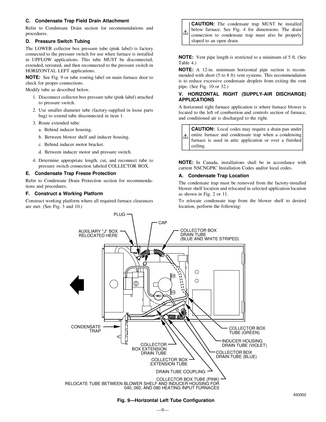
The LOWER collector box pressure tube (pink label) is factory connected to the pressure switch for use when furnace is installed in UPFLOW applications. This tube MUST be disconnected, extended, rerouted, and then reconnected to the pressure switch in HORIZONTAL LEFT applications.

NOTE: See Fig. 9 or tube routing label on main furnace door to check for proper connections.

Modify tube as described below.

1.Disconnect collector box pressure tube (pink label) attached to pressure switch.

2.Use smaller diameter tube (factory-supplied in loose parts bag) to extend tube disconnected in item 1.

3.Route extended tube:

a.Behind inducer housing.

b.Between blower shelf and inducer housing.

c.Behind inducer motor bracket.

d.Between inducer motor and pressure switch.

CAUTION: The condensate trap MUST be installed below furnace. See Fig. 4 for dimensions. The drain connection to condensate trap must also be properly sloped to an open drain.

NOTE: Vent pipe length is restricted to a minimum of 5 ft. (See Table 4.)

NOTE: A 12-in. minimum horizontal pipe section is recom- mended with short (5 to 8 ft) vent systems. This recommendation is to reduce excessive condensate droplets from exiting the vent pipe. (See Fig. 10 or 32.)

V.HORIZONTAL RIGHT (SUPPLY-AIR DISCHARGE) APPLICATIONS

A horizontal right furnace application is where furnace blower is located to the left of combustion and controls section of furnace, and conditioned air is discharged to the right.

CAUTION: Local codes may require a drain pan under entire furnace and condensate trap when a condensing furnace is used in attic application or over a finished ceiling.

4.Determine appropriate length, cut, and reconnect tube to pressure switch connection labeled COLLECTOR BOX.

E.Condensate Trap Freeze Protection

Refer to Condensate Drain Protection section for recommenda- tions and procedures.

F.Construct a Working Platform

Construct working platform where all required furnace clearances are met. (See Fig. 3 and 10.)

NOTE: In Canada, installations shall be in accordance with current NSCNGPIC Installation Codes and/or local codes.

A.Condensate Trap Location

The condensate trap must be removed from the factory-installed blower shelf location and relocated in selected application location as shown in Fig. 2 or 11.

To relocate condensate trap from the blower shelf to desired location, perform the following:

PLUG


CAP

AUXILIARY "J" BOX

COLLECTOR BOX

RELOCATED HERE

DRAIN TUBE


(BLUE AND WHITE STRIPED)

CONDENSATE

COLLECTOR BOX

TRAP

TUBE (GREEN)


COLLECTOR

INDUCER HOUSING

DRAIN TUBE (VIOLET)

BOX EXTENSION

COLLECTOR BOX

DRAIN TUBE


DRAIN TUBE (BLUE)

COLLECTOR BOX

EXTENSION TUBE

DRAIN TUBE COUPLING

COLLECTOR BOX TUBE (PINK) RELOCATE TUBE BETWEEN BLOWER SHELF AND INDUCER HOUSING FOR 040, 060, AND 080 HEATING INPUT FURNACES

A93302

Fig. 9ÐHorizontal Left Tube Configuration

Ð9Ð

Page 9
Image 9
Bryant 345MAV instruction manual Horizontal Right SUPPLY-AIR Discharge Applications, Construct a Working Platform, Ð9Ð

345MAV specifications

The Bryant 345MAV is a premier choice in the realm of residential heating and cooling systems, encapsulating advanced technologies, high efficiency, and remarkable performance. Designed for homeowners seeking reliability and comfort, this model exemplifies modern HVAC (Heating, Ventilation, and Air Conditioning) innovations.

One standout feature of the Bryant 345MAV is its impressive energy efficiency. With a high SEER (Seasonal Energy Efficiency Ratio) rating, it operates at peak levels while consuming less energy. This not only reduces utility bills but also supports environmental sustainability, making it an ideal selection for eco-conscious consumers. The model employs variable-speed technology, which allows the system to adjust its output based on current heating and cooling needs. As a result, it provides consistent indoor comfort while minimizing temperature fluctuations.

The Bryant 345MAV incorporates advanced refrigerant technologies designed for optimal performance. It uses R-410A refrigerant, which is known for its lower environmental impact compared to traditional refrigerants like R-22. This environmentally friendly aspect aligns with regulations aimed at reducing ozone depletion, thereby promoting a greener approach to heating and cooling.

Reliability is another hallmark of the Bryant 345MAV. Engineered with precision, this model features a durable build designed to withstand varying weather conditions. The system is equipped with a robust compressor that is engineered for longevity and minimal noise during operation. Homeowners will appreciate the quiet performance of the 345MAV, ensuring peace in their living spaces.

Comfort also extends to the user experience with the inclusion of a smart thermostat option. This integration allows homeowners to manage their heating and cooling systems remotely, enhancing convenience and control. Programmable settings can optimize energy use based on individual schedules, facilitating both comfort and savings.

In summary, the Bryant 345MAV is a top-tier solution for residential climate control, blending energy efficiency, innovative technology, and unmatched reliability. With its variable-speed operation, environmentally friendly refrigerant, and smart features, the 345MAV represents a significant advancement in the HVAC field. Homeowners investing in this model can expect a system that not only meets their heating and cooling needs but exceeds them in terms of efficiency and comfort.