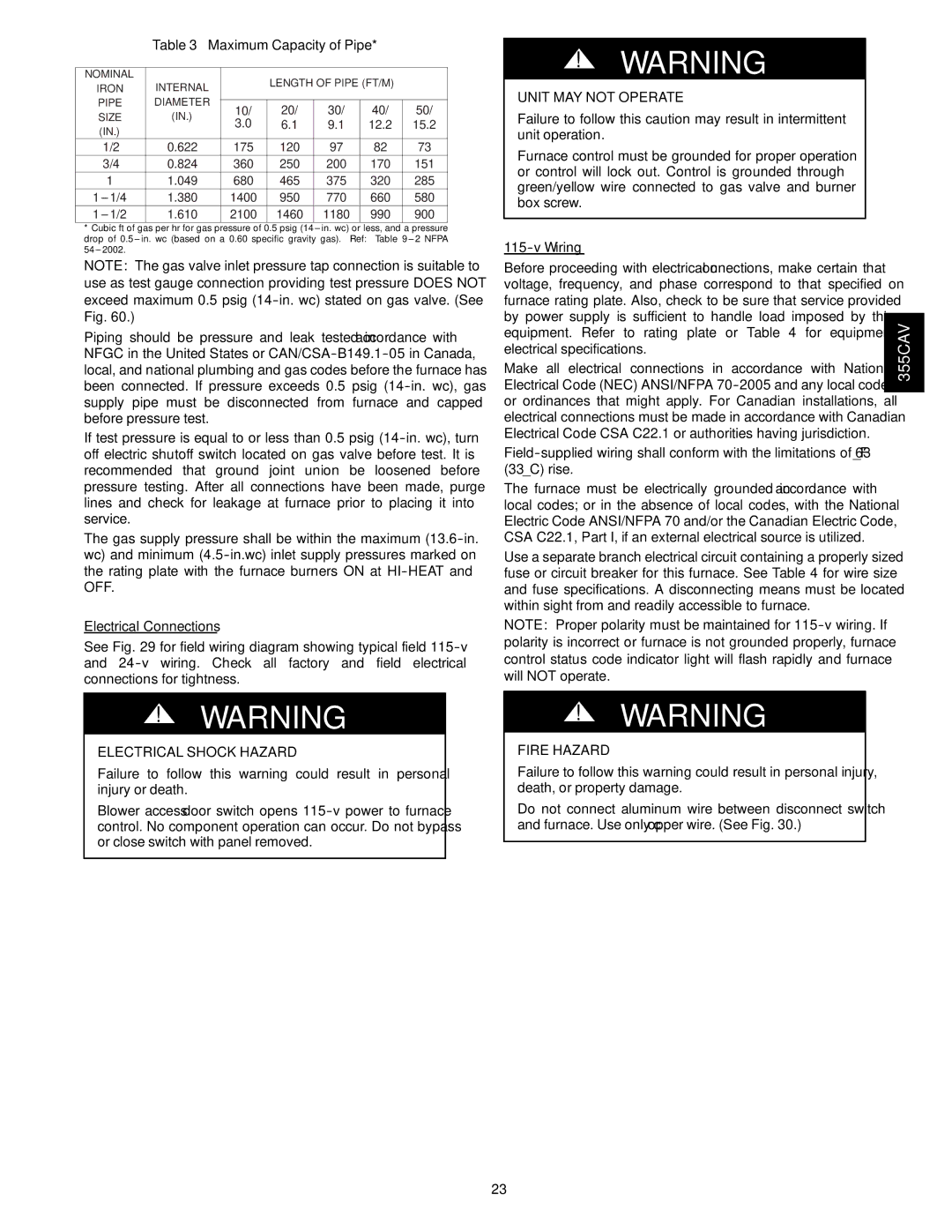
Table 3 – Maximum Capacity of Pipe*

NOMINAL

INTERNAL


LENGTH OF PIPE (FT/M)


IRON


PIPE

DIAMETER


10/

20/

30/

40/

50/

SIZE

(IN.)

3.0

6.1

9.1

12.2

15.2

(IN.)


1/2

0.622

175

120

97

82

73

3/4

0.824

360

250

200

170

151

1

1.049

680

465

375

320

285

1---1/4

1.380

1400

950

770

660

580

1---1/2

1.610

2100

1460

1180

990

900

*Cubic ft of gas per hr for gas pressure of 0.5 psig (14--- in. wc) or less, and a pressure drop of 0.5--- in. wc (based on a 0.60 specific gravity gas). Ref: Table 9--- 2 NFPA 54--- 2002.

NOTE: The gas valve inlet pressure tap connection is suitable to use as test gauge connection providing test pressure DOES NOT exceed maximum 0.5 psig (14-in. wc) stated on gas valve. (See Fig. 60.)

Piping should be pressure and leak tested in accordance with NFGC in the United States or CAN/CSA-B149.1-05 in Canada, local, and national plumbing and gas codes before the furnace has been connected. If pressure exceeds 0.5 psig (14-in. wc), gas supply pipe must be disconnected from furnace and capped before pressure test.

If test pressure is equal to or less than 0.5 psig (14-in. wc), turn off electric shutoff switch located on gas valve before test. It is recommended that ground joint union be loosened before pressure testing. After all connections have been made, purge lines and check for leakage at furnace prior to placing it into service.

The gas supply pressure shall be within the maximum (13.6-in. wc) and minimum (4.5-in.wc) inlet supply pressures marked on the rating plate with the furnace burners ON at HI-HEAT and OFF.

Electrical Connections

See Fig. 29 for field wiring diagram showing typical field 115-v and 24-v wiring. Check all factory and field electrical connections for tightness.

!WARNING

ELECTRICAL SHOCK HAZARD

Failure to follow this warning could result in personal injury or death.

Blower access door switch opens 115-v power to furnace control. No component operation can occur. Do not bypass or close switch with panel removed.

!WARNING

UNIT MAY NOT OPERATE

Failure to follow this caution may result in intermittent unit operation.

Furnace control must be grounded for proper operation or control will lock out. Control is grounded through green/yellow wire connected to gas valve and burner box screw.

115-v Wiring

Before proceeding with electrical connections, make certain that voltage, frequency, and phase correspond to that specified on furnace rating plate. Also, check to be sure that service provided by power supply is sufficient to handle load imposed by this equipment. Refer to rating plate or Table 4 for equipment electrical specifications.

Make all electrical connections in accordance with National Electrical Code (NEC) ANSI/NFPA 70-2005 and any local codes or ordinances that might apply. For Canadian installations, all electrical connections must be made in accordance with Canadian Electrical Code CSA C22.1 or authorities having jurisdiction.

Field-supplied wiring shall conform with the limitations of 63_F (33_C) rise.

The furnace must be electrically grounded in accordance with local codes; or in the absence of local codes, with the National Electric Code ANSI/NFPA 70 and/or the Canadian Electric Code, CSA C22.1, Part I, if an external electrical source is utilized.

Use a separate branch electrical circuit containing a properly sized fuse or circuit breaker for this furnace. See Table 4 for wire size and fuse specifications. A disconnecting means must be located within sight from and readily accessible to furnace.

NOTE: Proper polarity must be maintained for 115-v wiring. If polarity is incorrect or furnace is not grounded properly, furnace control status code indicator light will flash rapidly and furnace will NOT operate.

!WARNING

FIRE HAZARD

Failure to follow this warning could result in personal injury, death, or property damage.

Do not connect aluminum wire between disconnect switch and furnace. Use only copper wire. (See Fig. 30.)

355CAV

23

Page 23
Image 23
Bryant 355CAV installation instructions Maximum Capacity of Pipe, Electrical Shock Hazard, Wiring

355CAV specifications

The Bryant 355CAV is a state-of-the-art automated vertical machining center designed to enhance precision and efficiency in the manufacturing sector. Renowned for its robust construction, this machine is engineered to handle a broad spectrum of machining tasks, making it suitable for both small and large-scale production environments.

One of the standout features of the Bryant 355CAV is its advanced CNC control system, which provides users with exceptional ease of use. The intuitive user interface allows operators to program complex machining operations with minimal effort, significantly reducing setup times. The machine's high-speed spindle achieves impressive rotational speeds, which allows for quick material removal, ultimately optimizing productivity and throughput.

The Bryant 355CAV exhibits superior rigidity and stability due to its solid cast iron frame and carefully designed structural components. This construction minimizes vibrations during machining, ensuring that even the most intricate parts are produced with high accuracy. The machine's precision ground linear guideways further enhance its performance by providing smooth motion and high load capacity.

Equipped with a large work envelope, the Bryant 355CAV enables manufacturers to accommodate various part sizes and geometries. Additionally, its automatic tool changers can hold a variety of tools, thus facilitating quick transitions between different machining operations without requiring manual intervention. This flexibility is essential for meeting the diverse needs of modern manufacturing.

Another notable characteristic of the Bryant 355CAV is its energy-efficient design. It integrates modern technologies aimed at reducing power consumption while maintaining optimum performance. This environmentally conscious approach not only cuts operational costs but also aligns with the growing demand for sustainable manufacturing practices.

Moreover, the Bryant 355CAV features advanced monitoring capabilities, allowing operators to track machine performance in real time. Data analytics from these systems can be utilized to improve operational efficiency, reduce downtime, and enhance predictive maintenance protocols.

In summary, the Bryant 355CAV is a versatile, high-performance machining center that showcases cutting-edge features and technologies. Its combination of user-friendly controls, sturdy construction, energy efficiency, and advanced monitoring positions it as a vital asset for manufacturers aiming to elevate their productivity and precision in an increasingly competitive landscape.