COMBUSTION AIR

3/8" ID TUBE

INTAKE HOUSING

BURNER


BOX

3/16"

DRILLCOMBUSTION AIR PIPE

4

TRAP MIN

TO OPEN

DRAIN

A93035

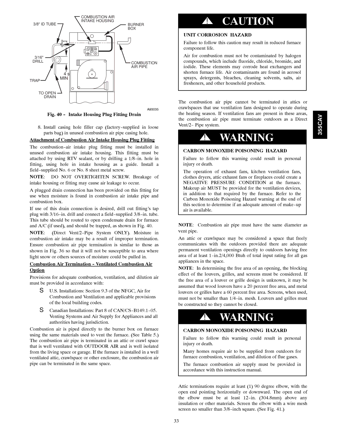
Fig. 40 - Intake Housing Plug Fitting Drain

8.Install casing hole filler cap (factory-supplied in loose parts bag) in unused combustion air pipe casing hole.

Attachment of Combustion Air Intake Housing Plug Fitting

The combustion-air intake plug fitting must be installed in unused combustion air intake housing. This fitting must be attached by using RTV sealant, or by drilling a 1/8-in. hole in fitting, using hole in intake housing as a guide. Install a field-supplied No. 6 or No. 8 sheet metal screw.

NOTE: DO NOT OVERTIGHTEN SCREW. Breakage of intake housing or fitting may cause air leakage to occur.

A plugged drain connection has been provided on this fitting for use when moisture is found in combustion air intake pipe and combustion box.

If use of this drain connection is desired, drill out fitting’s tap plug with 3/16-in. drill and connect a field-supplied 3/8-in. tube. This tube should be routed to open condensate drain for furnace and A/C (if used), and should be trapped, as shown in Fig. 40.

NOTE: (Direct Vent/2-Pipe System ONLY). Moisture in combustion air intake may be a result of improper termination. Ensure combustion air pipe termination is similar to those as shown in Fig. 36 so that it will not be susceptible to area where light snow or others sources of moisture could be pulled in.

Combustion Air Termination - Ventilated Combustion Air Option

Provisions for adequate combustion, ventilation, and dilution air must be provided in accordance with:

SU.S. Installations: Section 9.3 of the NFGC, Air for Combustion and Ventilation and applicable provisions of the local building codes.

SCanadian Installations: Part 8 of CAN/CS-B149.1-05. Venting Systems and Air Supply for Appliances and all authorities having jurisdiction.

Combustion air is piped directly to the burner box on furnace using the same materials used to vent the furnace. (See Table 5.) The combustion air pipe is terminated in an attic or crawl space that is well ventilated with OUTDOOR AIR and is well isolated from the living space or garage. If the furnace is installed in a well ventilated attic, crawlspace or other enclosure, the combustion air pipe can be terminated in the same space.

!CAUTION

UNIT CORROSION HAZARD

Failure to follow this caution may result in reduced furnace component life.

Air for combustion must not be contaminated by halogen compounds, which include fluoride, chloride, bromide, and iodide. These elements may corrode heat exchangers and shorten furnace life. Air contaminants are found in aerosol sprays, detergents, bleaches, cleaning solvents, salts, air fresheners, and other household products.

The combustion air pipe cannot be terminated in attics or crawlspaces that use ventilation fans designed to operate during the heating season. If ventilation fans are present in these areas, the combustion air pipe must terminate outdoors as a Direct Vent/2- Pipe system.

!WARNING

CARBON MONOXIDE POISONING HAZARD

Failure to follow this warning could result in personal injury or death.

The operation of exhaust fans, kitchen ventilation fans, clothes dryers, attic exhaust fans or fireplaces could create a NEGATIVE PRESSURE CONDITION at the furnace. Makeup air MUST be provided for the ventilation devices, in addition to that required by the furnace. Refer to the Carbon Monoxide Poisoning Hazard warning at the end of this section to determine if an adequate amount of make-up air is available.

NOTE: Combustion air pipe must have the same diameter as vent pipe.

An attic or crawlspace may be considered a space that freely communicates with the outdoors provided there are adequate permanent ventilation openings directly to outdoors having free area of at least 1-in.2/4,000 Btuh of total input rating for all gas appliances in the space.

NOTE: In determining the free area of an opening, the blocking effect of the louvers, grilles, and screens must be considered. If the free area of a louver or grille design is unknown, it may be assumed that wood louvers have a 20 percent free area, and metal louvers or grilles have a 60 percent free area. Screens, when used, must not be smaller than 1/4-in. mesh. Louvers and grilles must be constructed so they cannot be closed.

!WARNING

CARBON MONOXIDE POISONING HAZARD

Failure to follow this warning could result in personal injury or death.

Many homes require air to be supplied from outdoors for furnace combustion, ventilation, and dilution of flue gases.

The furnace combustion air supply must be provided in accordance with this instruction manual.

Attic terminations require at least (1) 90 degree elbow, with the open end pointing horizontally or downward. The open end of the elbow must be at least 12-in. (304.8mm) above any insulation or other materials. Screen the elbow with a wire mesh screen no smaller than 3/8-inch square. (See Fig. 41.)

355CAV

33

Page 33
Image 33
Bryant 355CAV installation instructions Attachment of Combustion Air Intake Housing Plug Fitting

355CAV specifications

The Bryant 355CAV is a state-of-the-art automated vertical machining center designed to enhance precision and efficiency in the manufacturing sector. Renowned for its robust construction, this machine is engineered to handle a broad spectrum of machining tasks, making it suitable for both small and large-scale production environments.

One of the standout features of the Bryant 355CAV is its advanced CNC control system, which provides users with exceptional ease of use. The intuitive user interface allows operators to program complex machining operations with minimal effort, significantly reducing setup times. The machine's high-speed spindle achieves impressive rotational speeds, which allows for quick material removal, ultimately optimizing productivity and throughput.

The Bryant 355CAV exhibits superior rigidity and stability due to its solid cast iron frame and carefully designed structural components. This construction minimizes vibrations during machining, ensuring that even the most intricate parts are produced with high accuracy. The machine's precision ground linear guideways further enhance its performance by providing smooth motion and high load capacity.

Equipped with a large work envelope, the Bryant 355CAV enables manufacturers to accommodate various part sizes and geometries. Additionally, its automatic tool changers can hold a variety of tools, thus facilitating quick transitions between different machining operations without requiring manual intervention. This flexibility is essential for meeting the diverse needs of modern manufacturing.

Another notable characteristic of the Bryant 355CAV is its energy-efficient design. It integrates modern technologies aimed at reducing power consumption while maintaining optimum performance. This environmentally conscious approach not only cuts operational costs but also aligns with the growing demand for sustainable manufacturing practices.

Moreover, the Bryant 355CAV features advanced monitoring capabilities, allowing operators to track machine performance in real time. Data analytics from these systems can be utilized to improve operational efficiency, reduce downtime, and enhance predictive maintenance protocols.

In summary, the Bryant 355CAV is a versatile, high-performance machining center that showcases cutting-edge features and technologies. Its combination of user-friendly controls, sturdy construction, energy efficiency, and advanced monitoring positions it as a vital asset for manufacturers aiming to elevate their productivity and precision in an increasingly competitive landscape.