APPLICATION DATA
569J
Operating limits
Maximum outdoor temperature . . . . . . . . . . . . . . . . 125_F Minimum
Range of acceptable saturation
suction temperature . . . . . . . . . . . . . . . . . . . 20 to 50_F Maximum discharge temperature . . . . . . . . . . . . . . 275_F Minimum discharge superheat . . . . . . . . . . . . . . . . . 60_F
NOTES:
1.Select air handler at no less than 300 cfm/ton (nomin- al condensing unit capacity).
2.Total combined draw of the
MINIMUM OUTDOOR-AIR OPERATING TEMPERATURE
UNIT |
| MINIMUM OUTDOOR TEMP (_F) | |
569J | Std |
| With MotorMaster I→ Control† |
07A | 35 |
|
|
08A | 35 |
|
|
12A | 35 |
|
|
14A | 35 |
|
|
16A | 35 |
| |
25A | 35 |
| |
|
| ||
12D | 35 |
|
|
14D | 35 |
|
|
16D | 35 |
|
|
25D | 35 |
|
|
†Wind baffles
Refrigerant piping
IMPORTANT: Do not bury refrigerant piping underground.
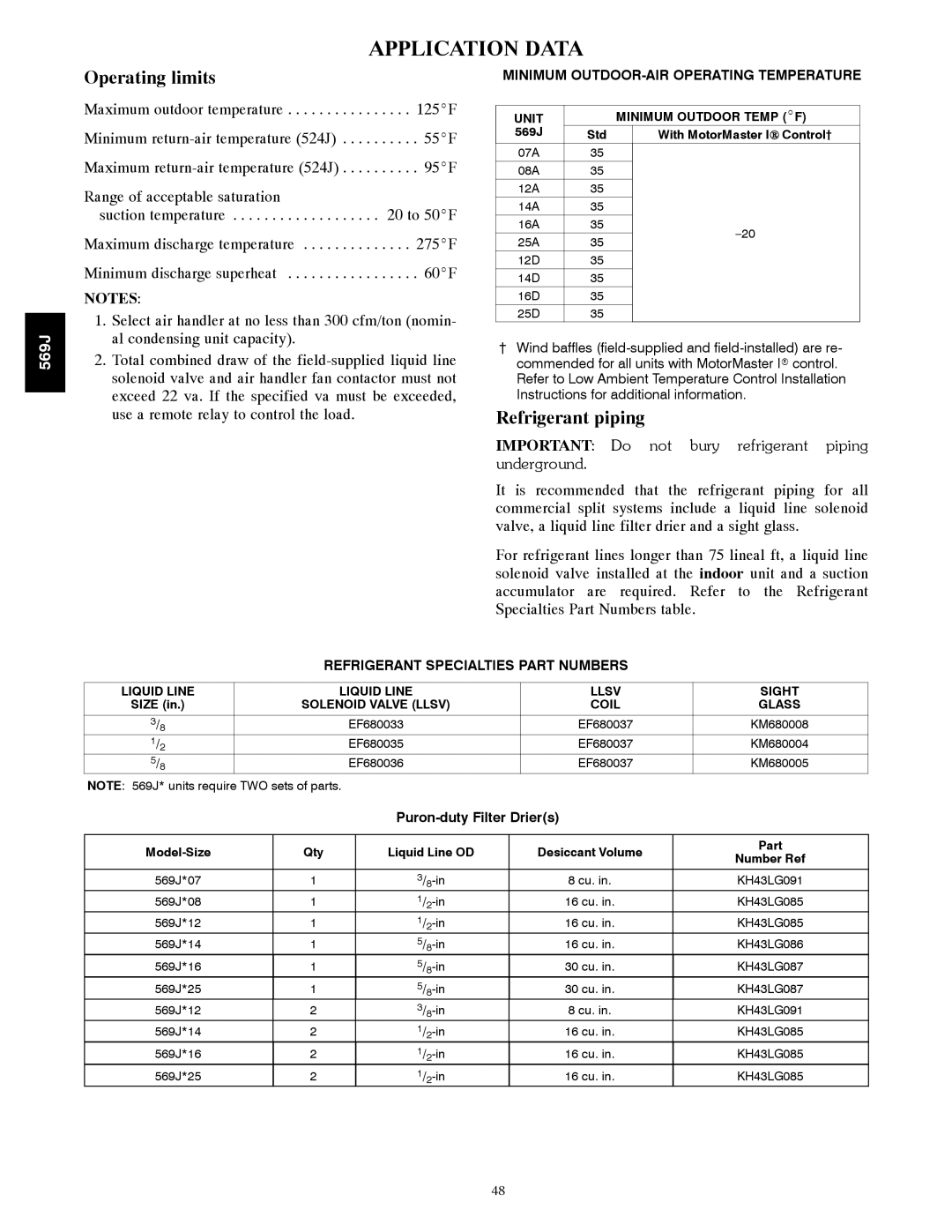
It is recommended that the refrigerant piping for all commercial split systems include a liquid line solenoid valve, a liquid line filter drier and a sight glass.
For refrigerant lines longer than 75 lineal ft, a liquid line solenoid valve installed at the indoor unit and a suction accumulator are required. Refer to the Refrigerant Specialties Part Numbers table.
REFRIGERANT SPECIALTIES PART NUMBERS
LIQUID LINE | LIQUID LINE | LLSV | SIGHT |
SIZE (in.) | SOLENOID VALVE (LLSV) | COIL | GLASS |
|
|
|
|
3/8 | EF680033 | EF680037 | KM680008 |
1/2 | EF680035 | EF680037 | KM680004 |
5/8 | EF680036 | EF680037 | KM680005 |
NOTE: 569J* units require TWO sets of parts.
|
|
| |
|
|
|
|
Qty | Liquid Line OD | Desiccant Volume | |
|
|
|
|
569J*07 | 1 | 8 cu. in. | |
569J*08 | 1 | 16 cu. in. | |
569J*12 | 1 | 16 cu. in. | |
569J*14 | 1 | 16 cu. in. | |
569J*16 | 1 | 30 cu. in. | |
569J*25 | 1 | 30 cu. in. | |
569J*12 | 2 | 8 cu. in. | |
569J*14 | 2 | 16 cu. in. | |
569J*16 | 2 | 16 cu. in. | |
569J*25 | 2 | 16 cu. in. | |
Part
Number Ref
KH43LG091
KH43LG085
KH43LG085
KH43LG086
KH43LG087
KH43LG087
KH43LG091
KH43LG085
KH43LG085
KH43LG085
48
