Manuals
/
Bryant
/
Household Appliance
/
Air Conditioner
Bryant
569J
manual
Dimensions
Models:
569J
1
9
60
60
Download
60 pages
1.74 Kb
6
7
8
9
10
11
12
13
Specification
Install
Typical Wiring Schematic
Typical Piping and Wiring
Dimension
Options and Accessories
Selection Procedure
Sound Power LEVELS, dB
Features / Benefits
Page 9
Image 9
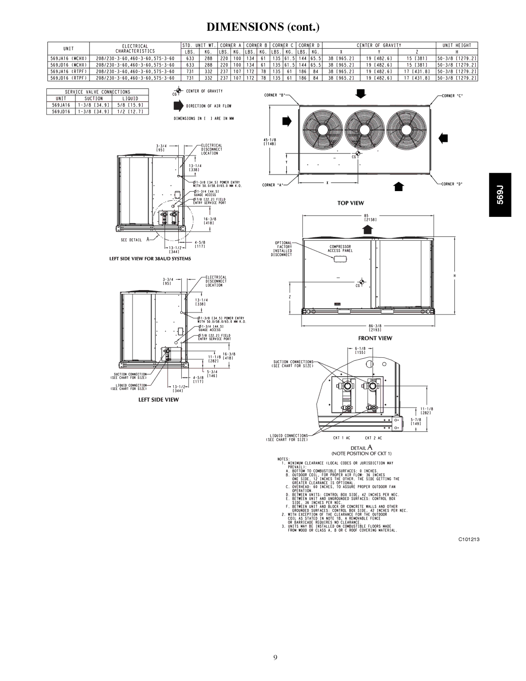
DIMENSIONS (cont.)
569J
C101213
9
Page 8
Page 10
Page 9
Image 9
Page 8
Page 10
Contents
Product Data
Features / Benefits
Indoor-air quality IAQ features
Factory-installed options FIOPs
Efficient operation
Controls for performance dependability
Table of Contents
Model Number Nomenclature
Unit Compressors Capacity Power EER Ieer Circuits Tons MBH
Sound Power LEVELS, dB
AHRI* Capacity Ratings
Cooling NOM NET Cooling
569J*07A 569J*08A 569J*12A 569J*14A 569J*16A
Physical Data
569J*07A
569J*12A 569J*14A 569J*16A
569J*25D
Dimensions
Dimensions
C101214
569J* factory-installed options
Options and Accessories
569J* Options and Accessories
Condenser Coil Options
524J factory-installed options
569J* field-installed accessories
524J field-installed accessories
524J Options and Accessories
Options and Accessories
524J with Economizer UV-C Germicidal Lamps
Selection Procedure
Controls
Operating sequences
Typical Wiring Schematic
Typical Wiring Schematic
Performance Data
AIR Temperature Entering Condenser F
569J*07A
569J*08A
569J*12D Dual Circuit
569J*12A
AIR Temp ENT Condenser F
100 105 115 120
569J*14D Dual Circuit
569J*14A
569J*16A
569J*16D Dual Circuit
105 115 125
569J*25D Dual Circuit
569J*25A
Combination Ratings
569J*07A 524J*07
569J*07A 524J*08
2250 Cfm
2600 Cfm
2625 Cfm
569J*08A 524J*08
3375 Cfm
3750 Cfm
Cfm
569J*08A 524J*12
3500
4000 Cfm
569J*12A 524J*12
3500 Cfm
5000 Cfm
569J*12 A- 524J*14
4300 Cfm
5700 Cfm
569J*12D 524J*12
569J*12D 524J*14
4375 Cfm
569J*14A 524J*14
5625 Cfm
6250 Cfm
5300 Cfm EA wb
569J*14A 524J*16
6000 Cfm
6800 Cfm
569J*14D 524J*14
5300 Cfm
569J*14D 524J*16
569J*16A 524J*16
7000 Cfm
569J*16A 524J*25
8000 Cfm
9000 Cfm
569J*16D- 524J*16
8000 Cfm EA wb
569J*16D 524J*25
569J*25A 524J*25
7000 Cfm EA wb
9000 Cfm EA wb
569J*25A- 524J*28
7500 Cfm
8750 Cfm
569J*25D- 524J*25
8750 Cfm EA wb
569J*25D- 524J*28
569J*07A Cooling with Powered Convenience Outlet
569J*07A Cooling Without Powered Convenience Outlet
569J*08A Cooling with Powered Convenience Outlet
569J*08A Cooling Without Powered Convenience Outlet
569J*12A Cooling with Powered Convenience Outlet
569J*12A Cooling Without Powered Convenience Outlet
569J*12D Cooling Without Powered Convenience Outlet
569J*12D Cooling with Powered Convenience Outlet
569J*14A Cooling with Powered Convenience Outlet
569J*14A Cooling Without Powered Convenience Outlet
569J*14D Cooling Without Powered Convenience Outlet
569J*14D Cooling with Powered Convenience Outlet
569J*16D Cooling Without Powered Convenience Outlet
569J*16A Cooling Without Powered Convenience Outlet
569J*16A Cooling with Powered Convenience Outlet
569J*16D Cooling with Powered Convenience Outlet
569J*25D Cooling Without Powered Convenience Outlet
569J*25A Cooling Without Powered Convenience Outlet
569J*25A Cooling with Powered Convenience Outlet
569J*25D Cooling with Powered Convenience Outlet
Application Data
Minimum OUTDOOR-AIR Operating Temperature
Operating limits
Refrigerant piping
569J* 07-14 Piping Recommendations SINGLE-CIRCUIT Unit
Model
569J 16-25 Piping Recommendations SINGLE-CIRCUIT Unit
569J*16
569J*25
Model 569J*12
569J 12-14 Piping Recommendations TWO-CIRCUIT Unit
569J 16-25 Piping Recommendations TWO-CIRCUIT Unit
Roof Installation and a Ceiling-Mounted Fan Coil
Typical Piping and Wiring
Roof Installation and a Vertical Discharge Fan Coil
Ground Level Installation and Vertical Discharge Fan Coil
Dual Condensing Units and a Dual Circuit Fan
System Description
Guide Specifications
569J
569J
Catalog No. PDS569J---03
Top
Page
Image
Contents