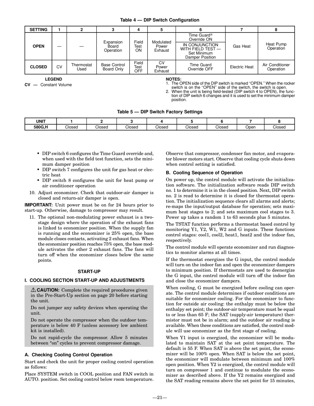
Table 4 Ð DIP Switch Con®guration

SETTING

1

2

3

4

5

6

7

8


Time Guard


Expansion

Field

Modulated

Override ON


OPEN


IN CONJUNCTION

Gas Heat

Heat Pump

Ð

Ð

Board

Test

Power

WITH FIELD TEST Ð

Operation


Operation

ON

Exhaust


Set Minimum


Damper Position


CLOSED


Thermostat

Base Control

Field

CV

Time Guard


Air Conditioner

CV

Test

Power

Electric Heat

Used

Board Only

Override OFF

Operation


OFF

Exhaust


LEGEND

CV Ð Constant Volume

NOTES:

1.The OPEN side of the DIP switch is marked ``OPEN.'' When the rocker switch is on the ``OPEN'' side of the switch, the switch is open.

2.When the unit is being ®eld-tested (DIP switch 4 to OPEN), the func- tion of DIP switch 6 changes and it is used to set the minimum damper position.

Table 5 Ð DIP Switch Factory Settings

UNIT

1

2

3

4

5

6

7

8

580G,H

Closed

Closed

Closed

Closed

Closed

Closed

Open

Closed

·DIP switch 6 con®gures the Time Guard override and, when used with the ®eld test function, sets the mini- mum damper position

·DIP switch 7 con®gures the unit for gas heat or elec- tric heat

·DIP switch 8 con®gures the unit for heat pump or air conditioner operation

10.Adjust economizer. Check that outdoor-air damper is closed and return-air damper is open.

IMPORTANT: Unit power must be on for 24 hours prior to start-up. Otherwise, damage to compressor may result.

11.The optional non-modulating power exhaust is a two- stage design where the operation of the exhaust fans is linked to economizer position. When the supply fan is running and the economizer is 25% open, the base module closes contacts, activating 2 exhaust fans. When the economizer position reaches 75% open, the base mod- ule activates the other 2 exhaust fans. The fans will turn off when the economizer closes below the same points.

START-UP

I. COOLING SECTION START-UP AND ADJUSTMENTS

CAUTION: Complete the required procedures given in the Pre-Start-Up section on page 20 before starting the unit.

Do not jumper any safety devices when operating the unit.

Do not operate the compressor when the outdoor tem- perature is below 40 F (unless accessory low ambient kit is installed).

Do not rapid-cycle the compressor. Allow 5 minutes between ``on'' cycles to prevent compressor damage.

A. Checking Cooling Control Operation

Start and check the unit for proper cooling control operation as follows:

Place SYSTEM switch in COOL position and FAN switch in AUTO. position. Set cooling control below room temperature.

Observe that compressor, condenser fan motor, and evapora- tor blower motors start. Observe that cooling cycle shuts down when control setting is satis®ed.

B. Cooling Sequence of Operation

On power up, the control module will activate the initializa- tion software. The initialization software reads DIP switch no. 1 to determine it is in the closed position. Next, DIP switch no. 2 is read to determine it is closed for thermostat opera- tion. The initialization sequence clears all alarms and alerts; re-maps the input/output database for operation; sets maxi- mum heat stages to 2; and sets maximum cool stages to 3. Power up takes a random 1 to 63 seconds plus 5 minutes.

The TSTAT function performs a thermostat based control by monitoring Y1, Y2, W1, W2 and G inputs. These functions control stages: cool1, cool2, heat1, heat2 and the indoor fan, respectively.

The control module will operate economizer and run diagnos- tics to monitor alarms at all times.

If the thermostat energizes the G input, the control module will turn on the indoor fan and open the economizer dampers to minimum position. If thermostats are used to deenergize the G input, the control module will turn off the indoor fan and close the economizer dampers.

When cooling, G must be energized before cooling can oper- ate. The control module determines if outdoor conditions are suitable for economizer cooling. For the economizer to func- tion for outside air cooling: the enthalpy must be below the enthalpy set point; the outdoor-air temperature must be equal to or less than 65 F; the SAT (supply-air temperature) ther- mistor must not be in alarm; and the outdoor air reading is available. When these conditions are satis®ed, the control mod- ule will use economizer as the ®rst stage of cooling.

When Y1 input is energized, the economizer will be modu- lated to maintain SAT at the set point temperature. The default is 55 F. When SAT is above the set point, the econo- mizer will be 100% open. When SAT is below the set point, the economizer will modulate between minimum and 100% open position. When Y2 is energized, the control module will turn on compressor 1 and continue to modulate the econo- mizer as described above. If the Y2 remains energized and the SAT reading remains above the set point for 15 minutes,

Ð21Ð

Page 21
Image 21
Bryant 580G manual DIP Switch Conguration, DIP Switch Factory Settings, START-UP Cooling Section START-UP and Adjustments

580G specifications

The Bryant 580G is a high-efficiency gas furnace designed to deliver optimal heating performance while maximizing energy savings. This model stands out in the Bryant product lineup due to its advanced features and robust technology, making it a popular choice for homeowners seeking reliable comfort in colder climates.

One of the key characteristics of the Bryant 580G is its efficiency rating. With an annual fuel utilization efficiency (AFUE) of up to 92.1%, this furnace ensures that a substantial portion of the fuel consumed is converted into heat, minimizing energy waste and reducing utility bills. This high-efficiency performance is particularly beneficial for those looking to lower their environmental footprint and operate a more sustainable home heating system.

The 580G uses a two-stage heating process, which allows it to operate at two levels of output. During mild weather, the furnace can run on a lower setting, providing gentle warmth while conserving energy. When temperatures drop, the system automatically ramps up to a higher output to maintain comfort. This feature not only enhances energy efficiency but also helps to eliminate temperature fluctuations, ensuring consistent warmth throughout the home.

Noise reduction technology is another remarkable aspect of the Bryant 580G. Equipped with a variable speed blower motor, this furnace operates quietly, providing a more peaceful indoor environment. The motor allows for customizable airflow, which further aids in maintaining an even temperature across different rooms and spaces.

The furnace is built with high-quality materials and features a compact design, making it a suitable option for various installation locations. Additionally, it is compatible with Bryant’s EcoNet Smart Home Management System, which enables homeowners to monitor and control their heating system remotely via a smartphone app. This integration enhances convenience and allows for timely adjustments to heating schedules, promoting energy savings.

Safety is a priority with the 580G. It features an integrated safety switch and a reliable flame sensor to ensure safe operation. With its durable construction and thoughtful engineering, the Bryant 580G is designed to withstand the demands of everyday use while providing peace of mind to homeowners.

In summary, the Bryant 580G gas furnace combines high efficiency, advanced technology, and user-friendly features. Its ability to operate quietly, adapt to temperature changes, and integrate with smart home technology makes it a leading choice for efficient home heating solutions. This furnace not only provides comfort but also offers long-term energy savings, making it a smart investment for any household.