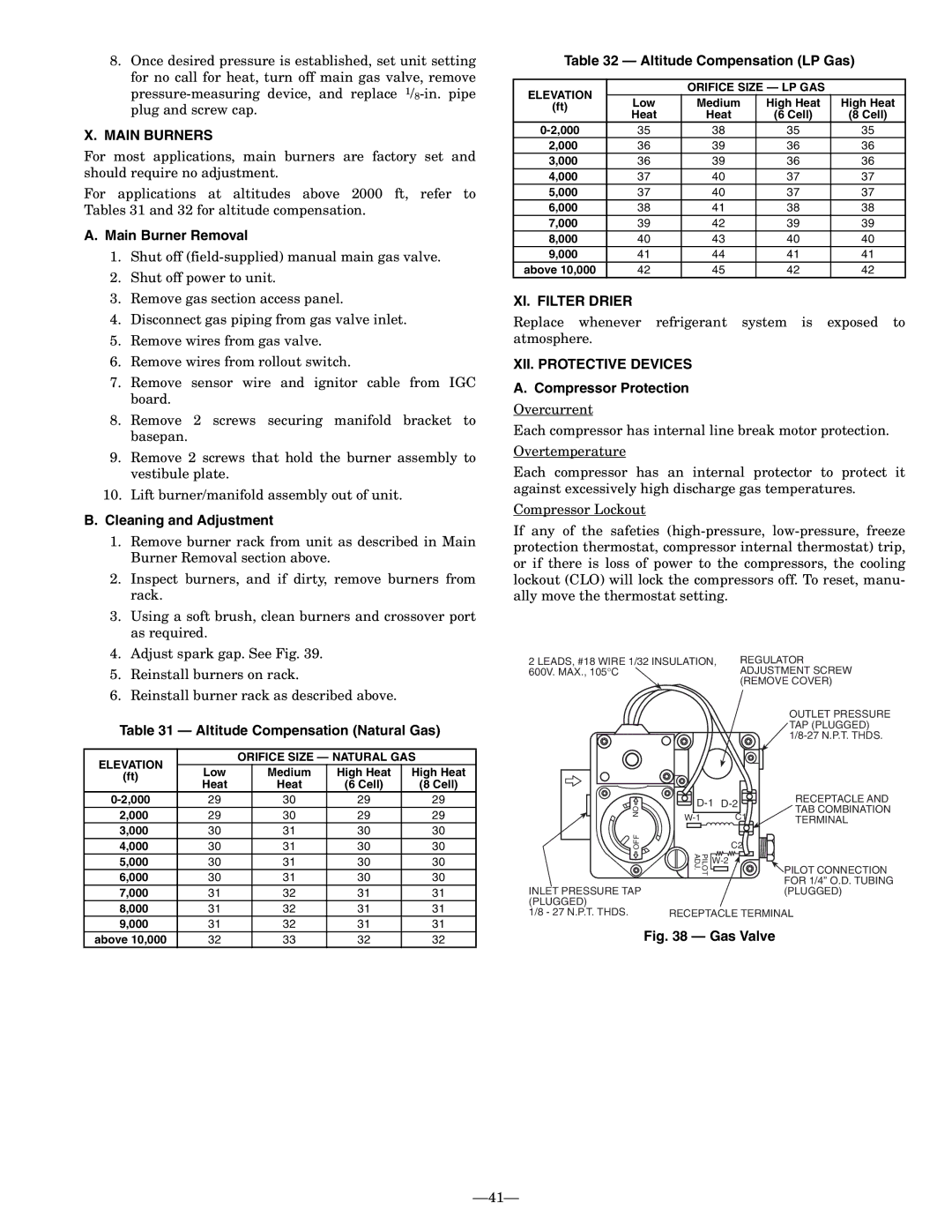
8.Once desired pressure is established, set unit setting for no call for heat, turn off main gas valve, remove pressure-measuring device, and replace 1/8-in. pipe plug and screw cap.

X.MAIN BURNERS

For most applications, main burners are factory set and should require no adjustment.

For applications at altitudes above 2000 ft, refer to Tables 31 and 32 for altitude compensation.

A.Main Burner Removal

1.Shut off (field-supplied) manual main gas valve.

2.Shut off power to unit.

3.Remove gas section access panel.

4.Disconnect gas piping from gas valve inlet.

5.Remove wires from gas valve.

6.Remove wires from rollout switch.

7.Remove sensor wire and ignitor cable from IGC board.

8.Remove 2 screws securing manifold bracket to basepan.

9.Remove 2 screws that hold the burner assembly to vestibule plate.

10.Lift burner/manifold assembly out of unit.

B.Cleaning and Adjustment

1.Remove burner rack from unit as described in Main Burner Removal section above.

2.Inspect burners, and if dirty, remove burners from rack.

3.Using a soft brush, clean burners and crossover port as required.

4.Adjust spark gap. See Fig. 39.

5.Reinstall burners on rack.

6.Reinstall burner rack as described above.

Table 31 — Altitude Compensation (Natural Gas)

ELEVATION


ORIFICE SIZE — NATURAL GAS

(ft)

Low


Medium

High Heat

High Heat

Heat


Heat

(6 Cell)

(8 Cell)


0-2,000

29


30

29

29

2,000

29


30

29

29

3,000

30


31

30

30

4,000

30


31

30

30

5,000

30


31

30

30

6,000

30


31

30

30

7,000

31


32

31

31

8,000

31


32

31

31

9,000

31


32

31

31

above 10,000

32


33

32

32

Table 32 — Altitude Compensation (LP Gas)

ELEVATION


ORIFICE SIZE — LP GAS


(ft)

Low

Medium

High Heat

High Heat

Heat

Heat

(6 Cell)

(8 Cell)


0-2,000

35

38

35

35

2,000

36

39

36

36

3,000

36

39

36

36

4,000

37

40

37

37

5,000

37

40

37

37

6,000

38

41

38

38

7,000

39

42

39

39

8,000

40

43

40

40

9,000

41

44

41

41

above 10,000

42

45

42

42

XI. FILTER DRIER

Replace whenever refrigerant system is exposed to atmosphere.

XII. PROTECTIVE DEVICES

A. Compressor Protection

Overcurrent

Each compressor has internal line break motor protection.

Overtemperature

Each compressor has an internal protector to protect it against excessively high discharge gas temperatures.

Compressor Lockout

If any of the safeties (high-pressure, low-pressure, freeze protection thermostat, compressor internal thermostat) trip, or if there is loss of power to the compressors, the cooling lockout (CLO) will lock the compressors off. To reset, manu- ally move the thermostat setting.

2 LEADS, #18 WIRE 1/32 INSULATION,

REGULATOR

600V. MAX., 105°C

ADJUSTMENT SCREW


(REMOVE COVER)

OUTLET PRESSURE TAP (PLUGGED) 1/8-27 N.P.T. THDS.


D-1

D-2

RECEPTACLE AND

ON

TAB COMBINATION

W-1


C1


TERMINAL


OFF


C2


PILOT ADJ.

W-2

PILOT CONNECTION


INLET PRESSURE TAP


FOR 1/4” O.D. TUBING


(PLUGGED)

(PLUGGED)


1/8 - 27 N.P.T. THDS.

RECEPTACLE TERMINAL

Fig. 38 — Gas Valve

41

Page 41
Image 41
Bryant 581A operation manual Main Burners, XI. Filter Drier, XII. Protective Devices

581A specifications

The Bryant 581A is a pivotal model in the realm of heating, ventilation, and air conditioning (HVAC) systems, known for its robust performance and energy efficiency. As part of the Bryant product lineup, the 581A offers a blend of innovative technologies combined with reliable engineering, making it a suitable choice for both residential and light commercial applications.

One of the standout features of the Bryant 581A is its outstanding energy efficiency. With a Seasonal Energy Efficiency Ratio (SEER) rating of up to 16, this model meets Energy Star qualifications, ensuring that homeowners can enjoy lower utility bills while helping to reduce their environmental footprint. The efficiency is further enhanced by the unit’s environmentally friendly refrigerant, which not only improves performance but also aligns with modern sustainability standards.

Another key characteristic of the Bryant 581A is its durable construction. Designed to withstand various weather conditions, the unit features a robust cabinet that protects internal components. This durability not only prolongs the lifespan of the system but also minimizes the need for frequent maintenance or repairs. The coil design is optimized for heat transfer efficiency, enhancing the unit's overall performance in both cooling and heating modes.

In terms of technology, the Bryant 581A incorporates advanced control systems that enable precise temperature regulation. The multi-stage cooling capabilities ensure that the system can adapt to varying temperature demands, providing comfort in all seasons. Additionally, the model is compatible with smart thermostats, allowing homeowners to control their HVAC system remotely via smartphone or other connected devices.

Noise reduction is another aspect where the Bryant 581A excels. Equipped with a variable-speed compressor and sound-dampening features, this model operates quietly, minimizing disruption in residential or office environments. This focus on acoustic comfort makes it an ideal choice for those who value a peaceful living or working space.

Overall, the Bryant 581A represents an excellent balance of efficiency, durability, and modern technology. With features aimed at enhancing user comfort and reducing operational costs, it stands out as a reliable solution in the competitive HVAC market. Whether for new installations or replacements, the Bryant 581A is a testament to the brand’s commitment to quality and innovation in home climate control.