Bryant 581A operation manual II. ECONOMI$ER IV Troubleshooting

Models: 581A

1 56
Download 56 pages 3.06 Kb
Page 50
Image 50

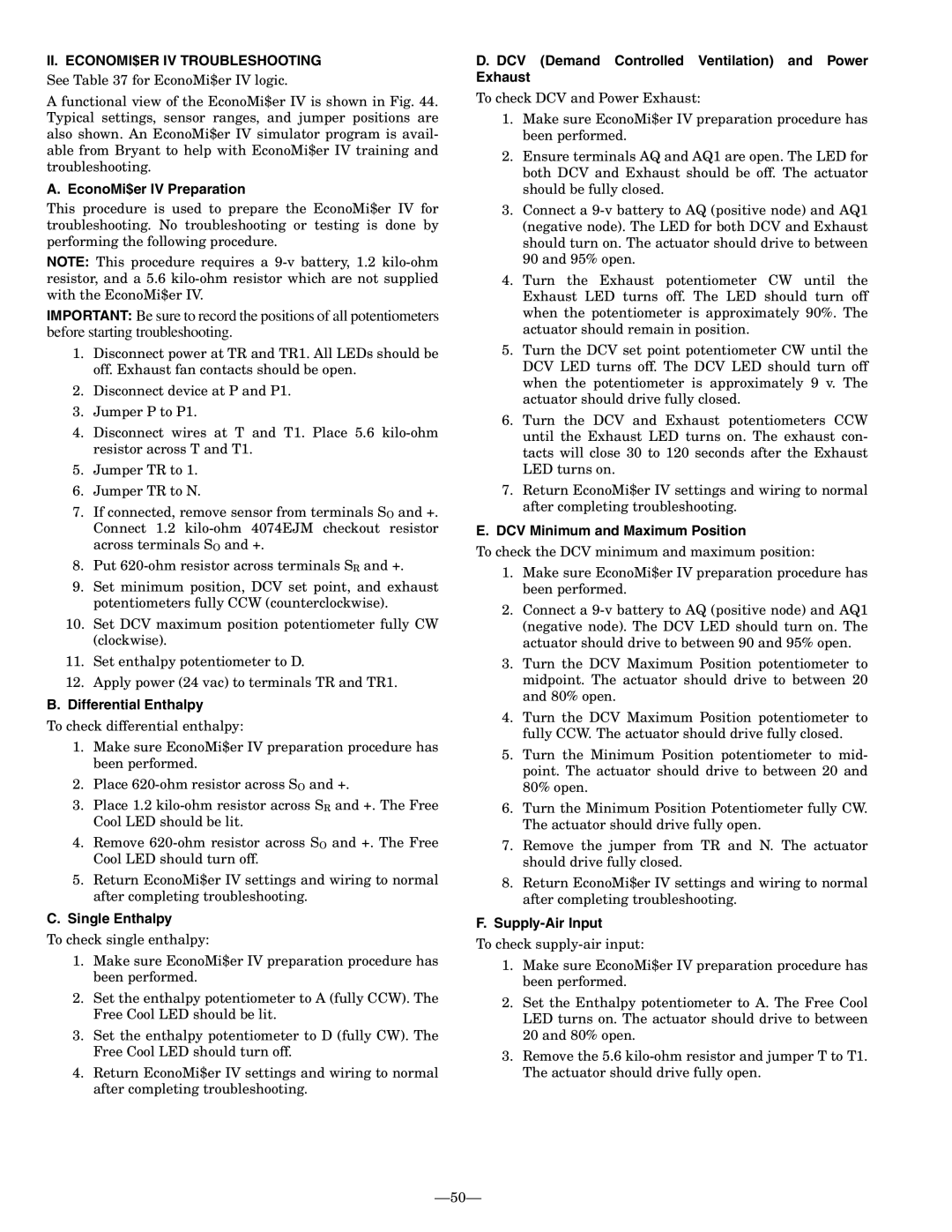
II.ECONOMI$ER IV TROUBLESHOOTING

See Table 37 for EconoMi$er IV logic.

A functional view of the EconoMi$er IV is shown in Fig. 44. Typical settings, sensor ranges, and jumper positions are also shown. An EconoMi$er IV simulator program is avail- able from Bryant to help with EconoMi$er IV training and troubleshooting.

A. EconoMi$er IV Preparation

This procedure is used to prepare the EconoMi$er IV for troubleshooting. No troubleshooting or testing is done by performing the following procedure.

NOTE: This procedure requires a 9-v battery, 1.2 kilo-ohm resistor, and a 5.6 kilo-ohm resistor which are not supplied with the EconoMi$er IV.

IMPORTANT: Be sure to record the positions of all potentiometers before starting troubleshooting.

1.Disconnect power at TR and TR1. All LEDs should be off. Exhaust fan contacts should be open.

2.Disconnect device at P and P1.

3.Jumper P to P1.

4.Disconnect wires at T and T1. Place 5.6 kilo-ohm resistor across T and T1.

5.Jumper TR to 1.

6.Jumper TR to N.

7.If connected, remove sensor from terminals SO and +. Connect 1.2 kilo-ohm 4074EJM checkout resistor across terminals SO and +.

8.Put 620-ohm resistor across terminals SR and +.

9.Set minimum position, DCV set point, and exhaust potentiometers fully CCW (counterclockwise).

10.Set DCV maximum position potentiometer fully CW (clockwise).

11.Set enthalpy potentiometer to D.

12.Apply power (24 vac) to terminals TR and TR1.

B. Differential Enthalpy

To check differential enthalpy:

1.Make sure EconoMi$er IV preparation procedure has been performed.

2.Place 620-ohm resistor across SO and +.

3.Place 1.2 kilo-ohm resistor across SR and +. The Free Cool LED should be lit.

4.Remove 620-ohm resistor across SO and +. The Free Cool LED should turn off.

5.Return EconoMi$er IV settings and wiring to normal after completing troubleshooting.

C.Single Enthalpy

To check single enthalpy:

1.Make sure EconoMi$er IV preparation procedure has been performed.

2.Set the enthalpy potentiometer to A (fully CCW). The Free Cool LED should be lit.

3.Set the enthalpy potentiometer to D (fully CW). The Free Cool LED should turn off.

4.Return EconoMi$er IV settings and wiring to normal after completing troubleshooting.

D. DCV (Demand Controlled Ventilation) and Power Exhaust

To check DCV and Power Exhaust:

1.Make sure EconoMi$er IV preparation procedure has been performed.

2.Ensure terminals AQ and AQ1 are open. The LED for both DCV and Exhaust should be off. The actuator should be fully closed.

3.Connect a 9-v battery to AQ (positive node) and AQ1 (negative node). The LED for both DCV and Exhaust should turn on. The actuator should drive to between 90 and 95% open.

4.Turn the Exhaust potentiometer CW until the Exhaust LED turns off. The LED should turn off when the potentiometer is approximately 90%. The actuator should remain in position.

5.Turn the DCV set point potentiometer CW until the DCV LED turns off. The DCV LED should turn off when the potentiometer is approximately 9 v. The actuator should drive fully closed.

6.Turn the DCV and Exhaust potentiometers CCW until the Exhaust LED turns on. The exhaust con- tacts will close 30 to 120 seconds after the Exhaust LED turns on.

7.Return EconoMi$er IV settings and wiring to normal after completing troubleshooting.

E.DCV Minimum and Maximum Position

To check the DCV minimum and maximum position:

1.Make sure EconoMi$er IV preparation procedure has been performed.

2.Connect a 9-v battery to AQ (positive node) and AQ1 (negative node). The DCV LED should turn on. The actuator should drive to between 90 and 95% open.

3.Turn the DCV Maximum Position potentiometer to midpoint. The actuator should drive to between 20 and 80% open.

4.Turn the DCV Maximum Position potentiometer to fully CCW. The actuator should drive fully closed.

5.Turn the Minimum Position potentiometer to mid- point. The actuator should drive to between 20 and 80% open.

6.Turn the Minimum Position Potentiometer fully CW. The actuator should drive fully open.

7.Remove the jumper from TR and N. The actuator should drive fully closed.

8.Return EconoMi$er IV settings and wiring to normal after completing troubleshooting.

F.Supply-Air Input

To check supply-air input:

1.Make sure EconoMi$er IV preparation procedure has been performed.

2.Set the Enthalpy potentiometer to A. The Free Cool LED turns on. The actuator should drive to between 20 and 80% open.

3.Remove the 5.6 kilo-ohm resistor and jumper T to T1. The actuator should drive fully open.

50

Page 50
Image 50
Bryant 581A operation manual II. ECONOMI$ER IV Troubleshooting

581A specifications

The Bryant 581A is a pivotal model in the realm of heating, ventilation, and air conditioning (HVAC) systems, known for its robust performance and energy efficiency. As part of the Bryant product lineup, the 581A offers a blend of innovative technologies combined with reliable engineering, making it a suitable choice for both residential and light commercial applications.

One of the standout features of the Bryant 581A is its outstanding energy efficiency. With a Seasonal Energy Efficiency Ratio (SEER) rating of up to 16, this model meets Energy Star qualifications, ensuring that homeowners can enjoy lower utility bills while helping to reduce their environmental footprint. The efficiency is further enhanced by the unit’s environmentally friendly refrigerant, which not only improves performance but also aligns with modern sustainability standards.

Another key characteristic of the Bryant 581A is its durable construction. Designed to withstand various weather conditions, the unit features a robust cabinet that protects internal components. This durability not only prolongs the lifespan of the system but also minimizes the need for frequent maintenance or repairs. The coil design is optimized for heat transfer efficiency, enhancing the unit's overall performance in both cooling and heating modes.

In terms of technology, the Bryant 581A incorporates advanced control systems that enable precise temperature regulation. The multi-stage cooling capabilities ensure that the system can adapt to varying temperature demands, providing comfort in all seasons. Additionally, the model is compatible with smart thermostats, allowing homeowners to control their HVAC system remotely via smartphone or other connected devices.

Noise reduction is another aspect where the Bryant 581A excels. Equipped with a variable-speed compressor and sound-dampening features, this model operates quietly, minimizing disruption in residential or office environments. This focus on acoustic comfort makes it an ideal choice for those who value a peaceful living or working space.

Overall, the Bryant 581A represents an excellent balance of efficiency, durability, and modern technology. With features aimed at enhancing user comfort and reducing operational costs, it stands out as a reliable solution in the competitive HVAC market. Whether for new installations or replacements, the Bryant 581A is a testament to the brand’s commitment to quality and innovation in home climate control.