4.Remove PTC from unit. Wait at least 10 minutes for PTC to cool to ambient temperature.
5.Measure resistance of PTC with ohmmeter as shown in Fig.13.
The cold resistance (RT) of any PTC device should be approxi- mately 100 – 180 percent of device ohm rating.
12.5–ohm PTC = 12.5–22.5 ohm resistance — beige color 25–ohm PTC = 25–45 ohm resistance — blue color 20–ohm PTC = 20–36 ohm resistance — blue color
If PTC resistance is appreciably less than rating or more than 200 percent higher than rating, device is defective.
If thermistor is good and compressor does not start:
1.Disconnect thermistor from starting circuit.
2.Give compressor a temporary capacitance boost (see next section).
3.Run compressor for 10 minutes, shut off, and allow system pressure to equalize.
4.Reconnect start thermistor.
5.Try restarting compressor without boost capacitor. If after 2 attempts compressor does not start, remove thermistor. Add an accessory start-capacitor relay package.
TEMPORARY CAPACITANCE BOOST
WARNING: Do not under any circumstances attach a temporary boost capacitor directly to the compressor terminals. Serious personal injury can result. Exercise extreme caution with this procedure when high-voltage power is on.
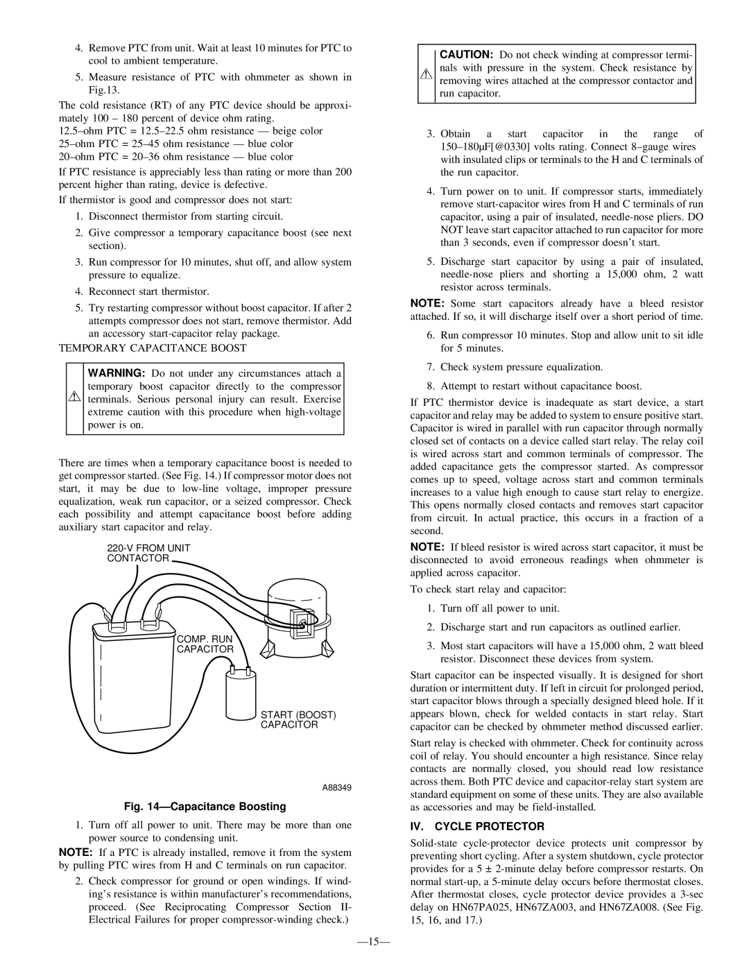
There are times when a temporary capacitance boost is needed to get compressor started. (See Fig. 14.) If compressor motor does not start, it may be due to low-line voltage, improper pressure equalization, weak run capacitor, or a seized compressor. Check each possibility and attempt capacitance boost before adding auxiliary start capacitor and relay.
220-V FROM UNIT CONTACTOR
 COMP. RUN
CAPACITOR
START (BOOST)
CAPACITOR
A88349
Fig. 14—Capacitance Boosting
1.Turn off all power to unit. There may be more than one power source to condensing unit.
NOTE: If a PTC is already installed, remove it from the system by pulling PTC wires from H and C terminals on run capacitor.
2.Check compressor for ground or open windings. If wind- ing’s resistance is within manufacturer’s recommendations, proceed. (See Reciprocating Compressor Section II- Electrical Failures for proper compressor-winding check.)
—15—
CAUTION: Do not check winding at compressor termi- nals with pressure in the system. Check resistance by removing wires attached at the compressor contactor and run capacitor.
3. Obtain a start capacitor in the range of 150–180µF[@0330] volts rating. Connect 8 –gauge wires with insulated clips or terminals to the H and C terminals of the run capacitor.
4.Turn power on to unit. If compressor starts, immediately remove start-capacitor wires from H and C terminals of run capacitor, using a pair of insulated, needle-nose pliers. DO NOT leave start capacitor attached to run capacitor for more than 3 seconds, even if compressor doesn’t start.
5.Discharge start capacitor by using a pair of insulated, needle-nose pliers and shorting a 15,000 ohm, 2 watt resistor across terminals.
NOTE: Some start capacitors already have a bleed resistor attached. If so, it will discharge itself over a short period of time.
6.Run compressor 10 minutes. Stop and allow unit to sit idle for 5 minutes.
7.Check system pressure equalization.
8.Attempt to restart without capacitance boost.
If PTC thermistor device is inadequate as start device, a start capacitor and relay may be added to system to ensure positive start. Capacitor is wired in parallel with run capacitor through normally closed set of contacts on a device called start relay. The relay coil is wired across start and common terminals of compressor. The added capacitance gets the compressor started. As compressor comes up to speed, voltage across start and common terminals increases to a value high enough to cause start relay to energize. This opens normally closed contacts and removes start capacitor from circuit. In actual practice, this occurs in a fraction of a second.
NOTE: If bleed resistor is wired across start capacitor, it must be disconnected to avoid erroneous readings when ohmmeter is applied across capacitor.
To check start relay and capacitor:
1.Turn off all power to unit.
2.Discharge start and run capacitors as outlined earlier.
3.Most start capacitors will have a 15,000 ohm, 2 watt bleed resistor. Disconnect these devices from system.
Start capacitor can be inspected visually. It is designed for short duration or intermittent duty. If left in circuit for prolonged period, start capacitor blows through a specially designed bleed hole. If it appears blown, check for welded contacts in start relay. Start capacitor can be checked by ohmmeter method discussed earlier.
Start relay is checked with ohmmeter. Check for continuity across coil of relay. You should encounter a high resistance. Since relay contacts are normally closed, you should read low resistance across them. Both PTC device and capacitor-relay start system are standard equipment on some of these units. They are also available as accessories and may be field-installed.
IV. CYCLE PROTECTOR
Solid-state cycle-protector device protects unit compressor by preventing short cycling. After a system shutdown, cycle protector provides for a 5 ± 2-minute delay before compressor restarts. On normal start-up, a 5-minute delay occurs before thermostat closes. After thermostat closes, cycle protector device provides a 3-sec delay on HN67PA025, HN67ZA003, and HN67ZA008. (See Fig. 15, 16, and 17.)