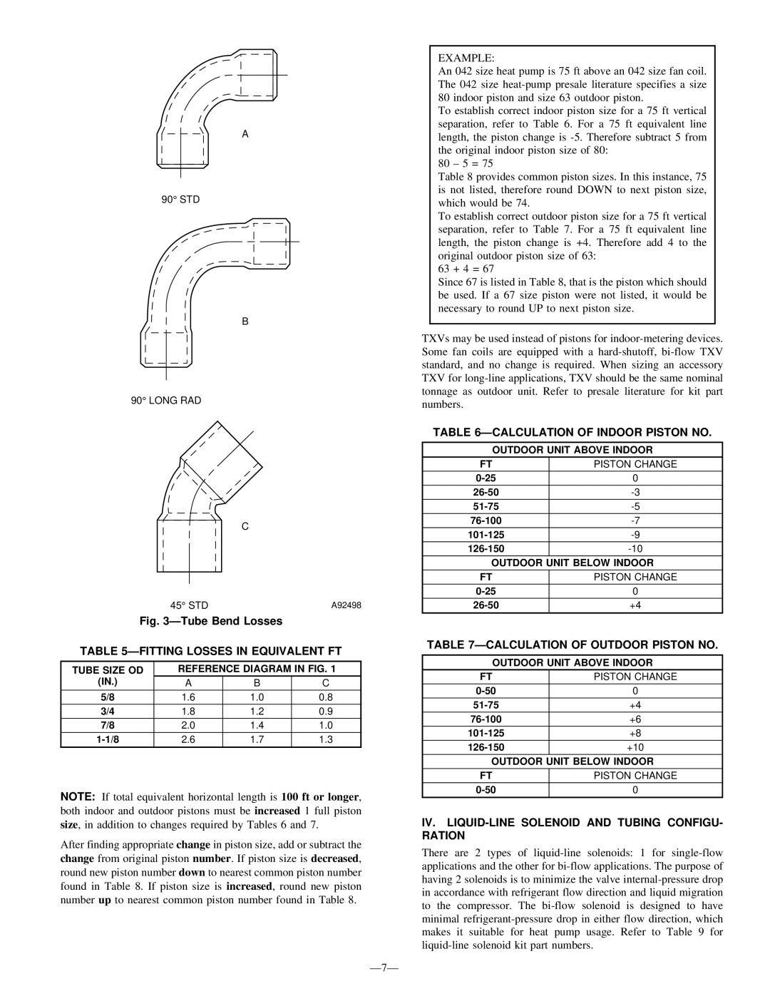
R-22 specifications
The Bryant R-22 stands out in the landscape of residential heating and cooling systems with its combination of efficiency, durability, and modern technology. Designed primarily for homeowners seeking comfortable climate control solutions, the R-22 model delivers consistent performance throughout varying seasonal extremes.One of the main features of the Bryant R-22 is its high energy efficiency. Rated with a SEER (Seasonal Energy Efficiency Ratio) that meets or exceeds industry standards, this air conditioning unit is designed to reduce energy consumption while providing optimal cooling. This not only helps in lowering monthly utility bills but also promotes environmentally responsible usage.
Another notable characteristic is the unit's durability. Constructed with a robust cabinet and high-quality components, the R-22 is built to withstand the rigors of daily use, with protective features that enhance its longevity. The cabinet comes with a powder-coated finish that resists corrosion and harsh weather conditions, ensuring that the unit stays functional and aesthetically pleasing for years.
The Bryant R-22 also incorporates advanced technology to improve user experience. One such innovation is the SmartSet technology, which allows homeowners to program their unit to optimize comfort levels according to their specific needs. This programmable capability enhances energy savings and ensures that the home remains at the desired temperature when residents are present.
Moreover, the unit features a Quiet Operating System that significantly reduces noise levels, making it suitable for residential areas where noise might be a concern. The design minimizes vibrations and optimizes airflow, creating a comfortable environment without disruptive sounds.
For added convenience, the Bryant R-22 is compatible with various thermostat options, including Wi-Fi-enabled models. This allows users to control their home's climate from anywhere using a smartphone app, facilitating effortless adjustments and monitoring of energy usage.
Finally, the Bryant R-22 is backed by a solid warranty, providing peace of mind for homeowners. This commitment to quality and customer satisfaction is a testament to Bryant’s dedication to producing reliable and efficient HVAC solutions. Overall, the Bryant R-22 is an exemplary choice for those looking to enhance their home comfort with the latest in HVAC technology.

