ATM Configuration
Due to a firmware anomaly, Connection Data will not be available in this window for the 9A128. Also, you will not be able to set any new connections or modify any existing connections from this window.
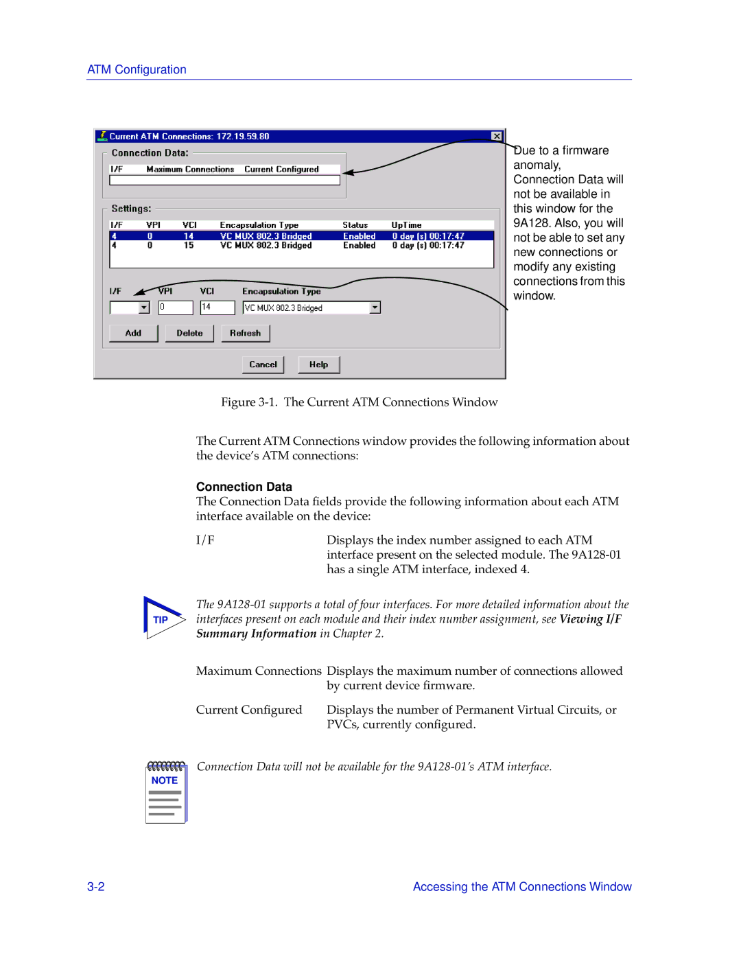
Figure 3-1. The Current ATM Connections Window
The Current ATM Connections window provides the following information about the device’s ATM connections:
Connection Data
The Connection Data fields provide the following information about each ATM interface available on the device:
I/F | Displays the index number assigned to each ATM |
| interface present on the selected module. The |
| has a single ATM interface, indexed 4. |
The
TIP interfaces present on each module and their index number assignment, see Viewing I/F Summary Information in Chapter 2.
Maximum Connections Displays the maximum number of connections allowed by current device firmware.
Current Configured | Displays the number of Permanent Virtual Circuits, or |
| PVCs, currently configured. |
NOTE |
Connection Data will not be available for the
Accessing the ATM Connections Window |