Chapter 2: Installation
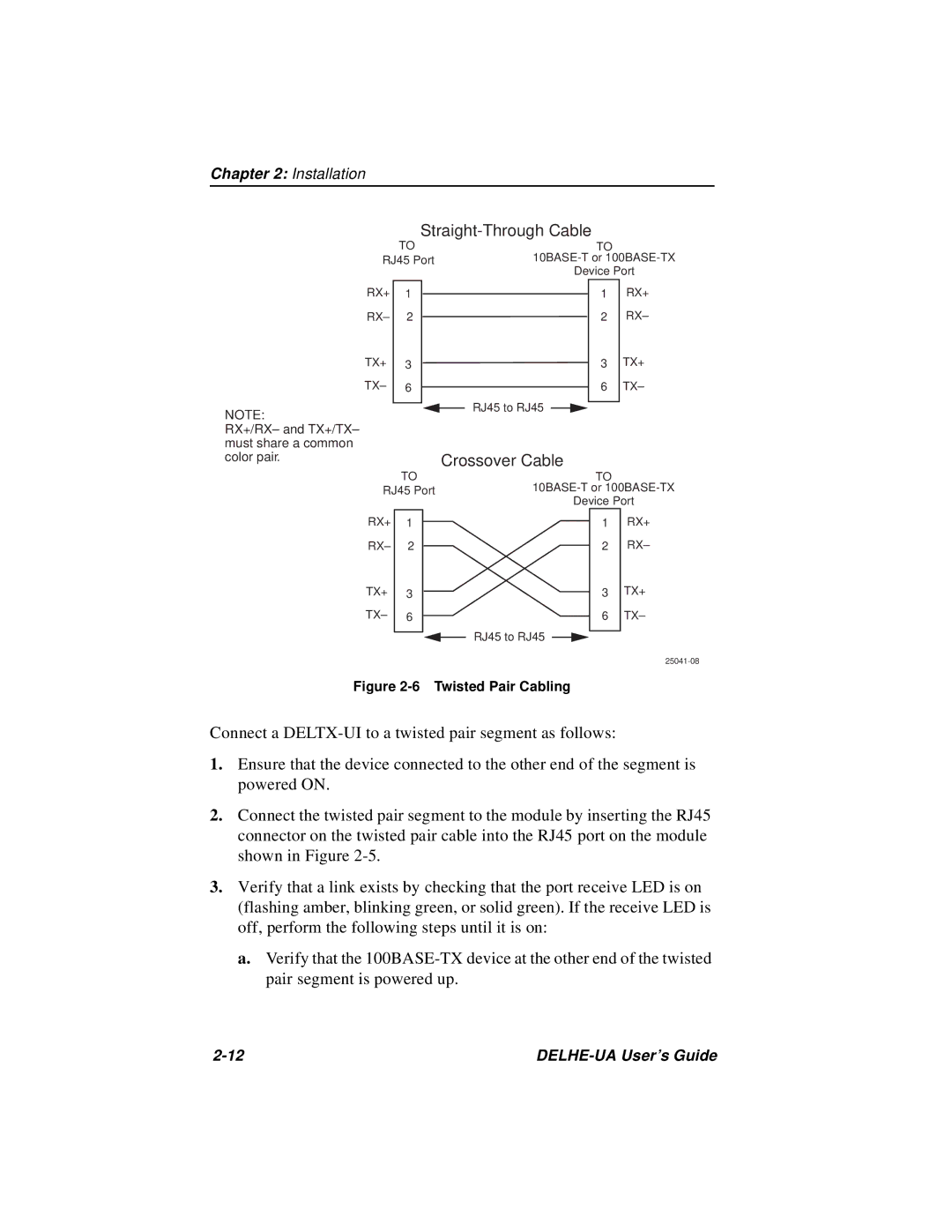
Straight-Through Cable
NOTE:
RX+/RX– and TX+/TX– must share a common color pair.
| TO |
|
|
|
| TO |
| |
RJ45 Port |
| |||||||
|
|
|
|
| Device Port | |||
RX+ | 1 |
|
|
|
|
| 1 | RX+ |
RX– | 2 |
|
|
|
|
| 2 | RX– |
TX+ | 3 |
|
|
|
|
| 3 | TX+ |
TX– | 6 |
|
|
|
|
| 6 | TX– |
|
|
|
| RJ45 to RJ45 |
|
|
|
|
|
|
|
|
| ||||
|
|
|
|
|
|
| ||
Crossover Cable
| TO |
|
|
|
|
| TO |
| ||
RJ45 Port |
| |||||||||
|
|
|
|
|
|
| Device Port | |||
RX+ | 1 |
|
|
|
|
|
|
| 1 | RX+ |
RX– | 2 |
|
|
|
|
|
|
| 2 | RX– |
TX+ | 3 |
|
|
|
|
|
|
| 3 | TX+ |
|
|
|
|
|
|
| ||||
|
|
|
|
|
|
| ||||
TX– | 6 |
|
|
|
|
|
|
| 6 | TX– |
|
|
|
|
| RJ45 to RJ45 |
|
|
|
| |
|
|
|
|
|
| |||||
|
|
|
|
|
|
|
| |||
Figure 2-6 Twisted Pair Cabling
Connect a
1.Ensure that the device connected to the other end of the segment is powered ON.
2.Connect the twisted pair segment to the module by inserting the RJ45 connector on the twisted pair cable into the RJ45 port on the module shown in Figure
3.Verify that a link exists by checking that the port receive LED is on (flashing amber, blinking green, or solid green). If the receive LED is off, perform the following steps until it is on:
a.Verify that the